23. FA TRANSPARENT FUNCTION
23.7 Precautions
23 - 89
17
ROBOT
CONT
ROLLER
CONN
E
C
TION
18
C
NC CONNECTION
19
ENER
GY M
EAS
URIN
G
UNIT/EL
EC
TRIC M
U
LT
I-
ME
ASUR
ING IN
STRU
MEN
T
CO
NNE
CTION
20
GOT
MUL
T
I-DROP
CONNECTION
21
MUL
TI
PL
E-GT1
4, G
T12,
GT
11
, GT
10
CO
NNECTIO
N FUNCTION
22
MUL
T
I-CHA
N
N
E
L
FUNCT
ION
23
F
A
TRANS
P
ARENT
FUNCTION
• Reading/Writing files of ladder edit
When PLC write is failed while using the FA
transparent function
The execution of PLC write using the FA transparent
function may be failed due to some reason such as
cable disconnection.
When this occurs, re-execute the PLC write from the
same personal computer, or reset the PLC CPU.
Restrictions on GX Developer during backup/
restore execution
(1) When reading/writing data from/to a PLC, monitoring a
PLC, and others are executed with GX Developer or
GX Works2 with the FA transparent function during the
backup/restore execution with the GOT, the backup/
restore is stopped.
Check that reading/writing data from/to the PLC,
monitoring the PLC, and others are not executed with
GX Developer or GX Works2 with the FA transparent
function. Execute the backup/restore with the GOT
again.
(2) When the backup/restore is executed with the GOT
while reading/writing data from/to a PLC, monitoring a
PLC, and others are executed with GX Developer or
GX Works2 with the FA transparent function, errors
occur on GX Developer or GX Works2.
The backup/restore with the GOT is correctly executed.
When connecting the GOT and personal
computer with modem connection
(1) Timeout time settings
When the FA transparent function is used with a
modem, it takes time for the initial communication with
PLC and GX Works2 or GX Developer and a timeout
may occur. In that case, set a longer time for the initial
communication timeout time for the GOT modem
connection tool.
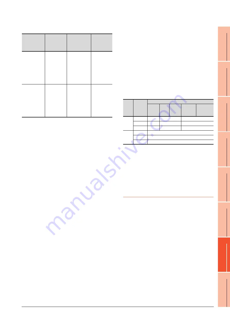
(2) Communication settings
When the FA transparent function is used via modem,
the communication setting differs depending on the
connection target of the GOT.
Set as follows.
*1
Communication settings of GX Works2/GX Developer are
set automatically, and setting is not required.
When connecting the ACPU and motion
controller CPU (A series) in bus connection
Do not execute write during RUN with GX Developer.
An error may occur in the PLC due to the write during
RUN, what may stop the PLC.
23.7.3 When using MT Developer,
MT Works2
When exiting MT Developer, MT Works2
For 45 seconds after GX Developer, MT Works2 has
been exited, the GOT continues monitoring at the same
speed as when the FA transparent function is working.
When PLC write is failed while using the FA
transparent function
The execution of PLC write using the FA transparent
function may be failed due to some reasons such as
cable disconnection.
When this occurs, re-execute the PLC write from the
same personal computer, or reset the motion controller
CPU.
When a cable disconnection has occurred
When the cable between the GOT and the motion CPU
is disconnected, it takes time until a timeout error
occurs in MT Developer.
Error messages
on GOT
Corrective
action on GOT
side
Error messages
on GX Developer
and GX Works2
Corrective
action on GX
Developer and
GX Works2
Read
With no file
operation being
executed on
GX Works3,
GX Works2 or
GX Developer,
re-execute the
file reading.
―
With no file
reading being
executed on
ladder edit,
execute the file
operation.
Write
With no file
operation being
executed on
GX Works3,
GX Works2 or
GX Developer,
re-execute the
file writing.
―
With no file
writing being
executed on
ladder edit,
execute the file
operation.
Target
of the
GOT
Setting
item
Setting target
GT
Designer3
GX
Works2
*1
GX
Developer
*1
GOT modem
connection
tool
Communication
settings of the
GOT
FXCPU
Data length
8bits
7bits
8bits
Parity
None
Even
None
Stop bit
1bit
1bit
1bit
QCPU
Data length
8bits
Parity
Odd
Stop bit
1bit
Summary of Contents for GT15
Page 2: ......
Page 34: ...A 32 ...
Page 92: ......
Page 110: ...2 18 2 DEVICE RANGE THAT CAN BE SET 2 9 MELSEC WS ...
Page 186: ...5 10 5 BUS CONNECTION 5 2 System Configuration ...
Page 218: ...5 42 5 BUS CONNECTION 5 4 Precautions ...
Page 254: ...6 36 6 DIRECT CONNECTION TO CPU 6 6 Precautions ...
Page 286: ...7 32 7 COMPUTER LINK CONNECTION 7 6 Precautions ...
Page 350: ...8 64 8 ETHERNET CONNECTION 8 5 Precautions ...
Page 368: ...9 18 9 MELSECNET H CONNECTION PLC TO PLC NETWORK 9 5 Precautions ...
Page 420: ...11 26 11 CC Link IE CONTROLLER NETWORK CONNECTION 11 5 Precautions ...
Page 440: ...12 20 12 CC Link IE FIELD NETWORK CONNECTION 12 5 Precautions ...
Page 490: ...13 50 13 CC Link CONNECTION INTELLIGENT DEVICE STATION 13 5 Precautions ...
Page 510: ......
Page 564: ...15 54 15 INVERTER CONNECTION 15 7 Precautions ...
Page 668: ......
Page 712: ...21 12 21 MULTIPLE GT14 GT12 GT11 GT10 CONNECTION FUNCTION 21 5 Precautions ...
Page 713: ...MULTI CHANNEL FUNCTION 22 MULTI CHANNEL FUNCTION 22 1 ...
Page 714: ......
Page 760: ...22 46 22 MULTI CHANNEL FUNCTION 22 5 Multi channel Function Check Sheet ...
Page 761: ...FA TRANSPARENT FUNCTION 23 FA TRANSPARENT FUNCTION 23 1 ...
Page 762: ......
Page 860: ...REVISIONS 4 ...
Page 863: ......


