5. BUS CONNECTION
5.4 Precautions
5 - 39
1
P
R
EP
ARA
T
OR
Y
P
R
OCEDURES
FOR
MONIT
O
R
ING
2
D
E
VICE RA
NGE
T
H
A
T
CAN
B
E
SET
3
ACCESS
RA
N
G
E
F
O
R MONIT
O
R
ING
4
HOW T
O
MONIT
O
R
REDUNT
ANT
SYS
TEM
5
BUS CONNECTION
6
DIR
E
CT
CONNECTION T
O
CPU
7
COMP
UT
E
R
L
INK
CONNE
C
T
ION
8
E
T
HE
RN
E
T
CONN
E
C
T
ION
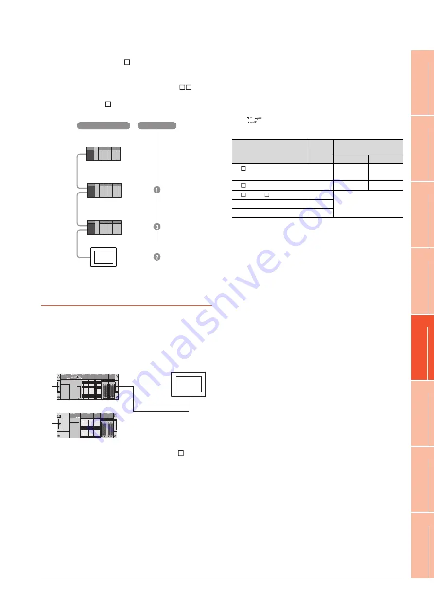
(4) When using the QA1S6 B extension base unit
A GOT is physically connected to the last of all
extension base units. In the Stage No. setting, however,
assign the GOT as a stage next to the last Q
B type
extension base unit.
Assign the QA1S6 B type extension base unit as a
stage next to the GOT.
5.4.11 When connecting to a
QnA(S)CPU or An(S)CPU type
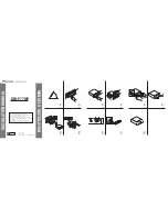
(1) When connecting with a QnASCPU type and an
AnSCPU type
A GOT can be connected to an extension connector on
only one side of the main base unit.
(Concurrently connecting GOTs to extension
connectors on both sides is not allowed)
(2) In the case of Q4A(R)CPU, Q3ACPU, A3 CPU,
A4UCPU
Empty I/O slots are required within the max. number of
extension stages.
(3) For A0J2HCPU
Assign the GOT to the I/O slots 0 to 3 of extension
stage 1.
(4) In the case of CPUs other than (2) (3) above
Even if the max. number of stages are used with no
empty I/O slots, when there is a free space of 32 I/O
points or more, a GOT can be connected under the
following communication interface setting.
For the communication interface setting, refer to the
following.
5.3.1 Setting communication interface
(Communication settings)
Q38B
Main base unit
Q68B
Extension base unit
QA1S68B
Extension base unit
Stage No.
Connection method
When connecting to
Max.
stage
No.
Communication interface
setting
Stage No.
Slot No.
A1 CPU/A2USCPU(-S1)
/QnAS(H)CPU(-S1)
1
2
0
A2 CPU/Q2ACPU
3
4
0
A3 CPU/A4 CPU
7
Cannot be used
Q3ACPU/Q4ACPU
7
A0J2HCPU
1
Summary of Contents for GT15
Page 2: ......
Page 34: ...A 32 ...
Page 92: ......
Page 110: ...2 18 2 DEVICE RANGE THAT CAN BE SET 2 9 MELSEC WS ...
Page 186: ...5 10 5 BUS CONNECTION 5 2 System Configuration ...
Page 218: ...5 42 5 BUS CONNECTION 5 4 Precautions ...
Page 254: ...6 36 6 DIRECT CONNECTION TO CPU 6 6 Precautions ...
Page 286: ...7 32 7 COMPUTER LINK CONNECTION 7 6 Precautions ...
Page 350: ...8 64 8 ETHERNET CONNECTION 8 5 Precautions ...
Page 368: ...9 18 9 MELSECNET H CONNECTION PLC TO PLC NETWORK 9 5 Precautions ...
Page 420: ...11 26 11 CC Link IE CONTROLLER NETWORK CONNECTION 11 5 Precautions ...
Page 440: ...12 20 12 CC Link IE FIELD NETWORK CONNECTION 12 5 Precautions ...
Page 490: ...13 50 13 CC Link CONNECTION INTELLIGENT DEVICE STATION 13 5 Precautions ...
Page 510: ......
Page 564: ...15 54 15 INVERTER CONNECTION 15 7 Precautions ...
Page 668: ......
Page 712: ...21 12 21 MULTIPLE GT14 GT12 GT11 GT10 CONNECTION FUNCTION 21 5 Precautions ...
Page 713: ...MULTI CHANNEL FUNCTION 22 MULTI CHANNEL FUNCTION 22 1 ...
Page 714: ......
Page 760: ...22 46 22 MULTI CHANNEL FUNCTION 22 5 Multi channel Function Check Sheet ...
Page 761: ...FA TRANSPARENT FUNCTION 23 FA TRANSPARENT FUNCTION 23 1 ...
Page 762: ......
Page 860: ...REVISIONS 4 ...
Page 863: ......


