20. GOT MULTI-DROP CONNECTION
20.6 Setting of Serial Multi-Drop Connection Unit
20 - 27
17
ROBOT
CONT
ROLLER
CONN
E
C
TION
18
C
NC CONNECTION
19
ENER
GY M
EAS
URIN
G
UNIT/EL
EC
TRIC M
U
LT
I-
ME
ASUR
ING IN
STRU
MEN
T
CO
NNE
CTION
20
GOT
MUL
T
I-DROP
CONNECTION
21
MUL
TI
PL
E-GT1
4, G
T12,
GT
11
, GT
10
CO
NNECTIO
N FUNCTION
22
MUL
T
I-CHA
N
N
E
L
FUNCT
ION
23
F
A
TRANS
P
ARENT
FUNCTION
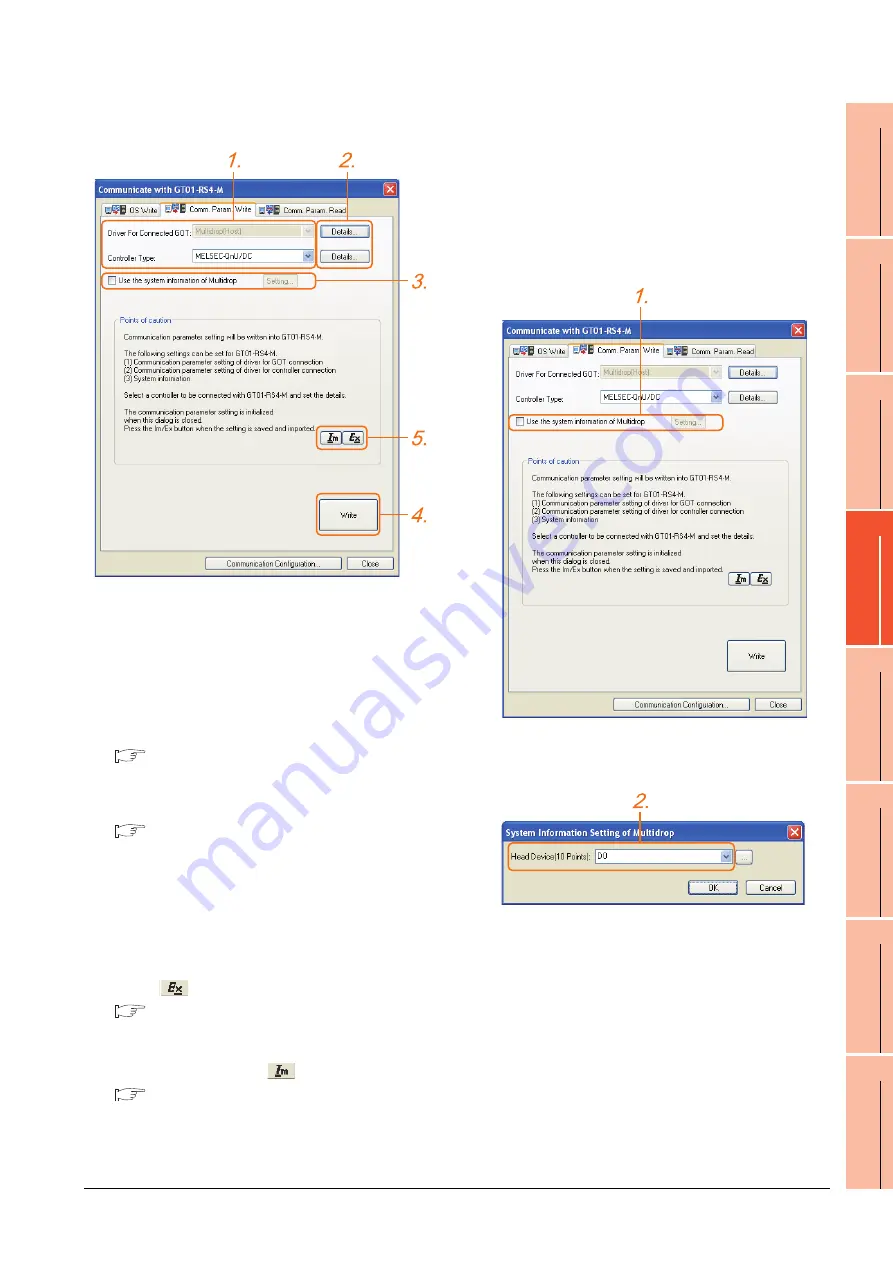
Controller setting
1.
Set the following to the driver for the connected
equipment.
• Connection type dependent
The driver for connection with the GOT is fixed to the
following one.
• Multi-drop(Host)
2.
Perform the detailed settings for the driver.
■
3.
Set [Use the system information of Multidrop] as
necessary.
■
Setting the multi-drop system information
4.
Click the [Write] button when settings are completed.
5.
If the [Communication with GT01-RS4-M] dialog box
is closed, communication setting contents for GT01-
RS4-M does not remain.
• To maintain the communication setting contents,
click
(export).
■
Exporting/Importing the communication
setting contents
• To use communication setting contents which are
saved previously, click
(import).
■
Exporting/Importing the communication
setting contents
Setting the multi-drop system information
function
When checking the connection status of each GOT
which is connected to GT01-RS4-M on the PLC side,
set the multi-drop system information function.
The GOT connection status is stored in the PLC side
word device.
(1) Setting on the PLC side word device
1.
Select [Use the system information of Multidrop] and
click the [Set] button. The following dialog window is
displayed.
2.
Set the PLC side word device to [Head Device (10
Points)]. In this example, "D0" is set.
Summary of Contents for GT15
Page 2: ......
Page 34: ...A 32 ...
Page 92: ......
Page 110: ...2 18 2 DEVICE RANGE THAT CAN BE SET 2 9 MELSEC WS ...
Page 186: ...5 10 5 BUS CONNECTION 5 2 System Configuration ...
Page 218: ...5 42 5 BUS CONNECTION 5 4 Precautions ...
Page 254: ...6 36 6 DIRECT CONNECTION TO CPU 6 6 Precautions ...
Page 286: ...7 32 7 COMPUTER LINK CONNECTION 7 6 Precautions ...
Page 350: ...8 64 8 ETHERNET CONNECTION 8 5 Precautions ...
Page 368: ...9 18 9 MELSECNET H CONNECTION PLC TO PLC NETWORK 9 5 Precautions ...
Page 420: ...11 26 11 CC Link IE CONTROLLER NETWORK CONNECTION 11 5 Precautions ...
Page 440: ...12 20 12 CC Link IE FIELD NETWORK CONNECTION 12 5 Precautions ...
Page 490: ...13 50 13 CC Link CONNECTION INTELLIGENT DEVICE STATION 13 5 Precautions ...
Page 510: ......
Page 564: ...15 54 15 INVERTER CONNECTION 15 7 Precautions ...
Page 668: ......
Page 712: ...21 12 21 MULTIPLE GT14 GT12 GT11 GT10 CONNECTION FUNCTION 21 5 Precautions ...
Page 713: ...MULTI CHANNEL FUNCTION 22 MULTI CHANNEL FUNCTION 22 1 ...
Page 714: ......
Page 760: ...22 46 22 MULTI CHANNEL FUNCTION 22 5 Multi channel Function Check Sheet ...
Page 761: ...FA TRANSPARENT FUNCTION 23 FA TRANSPARENT FUNCTION 23 1 ...
Page 762: ......
Page 860: ...REVISIONS 4 ...
Page 863: ......


