


3-30
F60 Feeder Protection System
GE Multilin
3.2 WIRING
3 HARDWARE
3
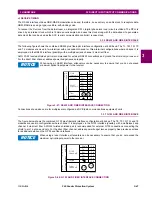
To avoid loop currents, ground the shield at only one point. If other system considerations require the shield to be grounded
at more than one point, install resistors (typically 100 ohms) between the shield and ground at each grounding point. Each
relay needs to be daisy-chained to the next one in the link. A maximum of 32 relays can be connected in this manner with-
out exceeding driver capability. For larger systems, additional serial channels must be added. It is also possible to use com-
mercially available repeaters to have more than 32 relays on a single channel. Avoid star or stub connections entirely.
Lightning strikes and ground surge currents can cause large momentary voltage differences between remote ends of the
communication link. For this reason, surge protection devices are internally provided at both communication ports. An iso-
lated power supply with an optocoupled data interface also acts to reduce noise coupling. To ensure maximum reliability, all
equipment should have similar transient protection devices installed.
Terminate both ends of the RS485 circuit with an impedance as shown below.
Figure 3–29: RS485 SERIAL CONNECTION
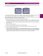
c) 100BASE-FX FIBER OPTIC PORTS
Ensure that the dust covers are installed when the fiber is not in use. Dirty or scratched connectors can lead to high losses
on a fiber link.
The fiber optic communication ports allow for fast and efficient communications between relays at 100 Mbps. Optical fiber
can be connected to the relay supporting a wavelength of 1310 nm in multi-mode.
SCADA / PLC / computer
Optocoupler
Data
UR-series device
Shield
827757AA.CDR
Last device
Z (*)
T
Z (*) Terminating impedance at
T
each end (typically 120 Ω and 1 nF)
Twisted pair
RS485 +
RS485 –
COMP 485COM
Relay
Relay
Ground shield at SCADA / PLC /
computer
only
or at
UR-series device
only
Data
Optocoupler
Up to 32 devices,
maximum 4000 feet
(1200 m)
Z (*)
T
RS485 +
RS485 –
COMP 485COM
RS485 +
RS485 –
COMP 485COM
COM
Summary of Contents for F60
Page 10: ...x F60 Feeder Protection System GE Multilin TABLE OF CONTENTS ...
Page 30: ...1 20 F60 Feeder Protection System GE Multilin 1 5 USING THE RELAY 1 GETTING STARTED 1 ...
Page 138: ...4 28 F60 Feeder Protection System GE Multilin 4 2 FACEPLATE INTERFACE 4 HUMAN INTERFACES 4 ...
Page 454: ...5 316 F60 Feeder Protection System GE Multilin 5 10 TESTING 5 SETTINGS 5 ...
Page 500: ...7 14 F60 Feeder Protection System GE Multilin 7 1 COMMANDS 7 COMMANDS AND TARGETS 7 ...
Page 508: ...8 8 F60 Feeder Protection System GE Multilin 8 2 FAULT LOCATOR 8 THEORY OF OPERATION 8 ...
Page 522: ...10 12 F60 Feeder Protection System GE Multilin 10 6 DISPOSAL 10 MAINTENANCE 10 ...
Page 660: ...B 116 F60 Feeder Protection System GE Multilin B 4 MEMORY MAPPING APPENDIX B B ...
Page 706: ...E 10 F60 Feeder Protection System GE Multilin E 1 IEC 60870 5 104 APPENDIX E E ...
Page 718: ...F 12 F60 Feeder Protection System GE Multilin F 2 DNP POINT LISTS APPENDIX F F ...
Page 728: ...H 8 F60 Feeder Protection System GE Multilin H 2 ABBREVIATIONS APPENDIX H H Z Impedance Zone ...
Page 730: ...H 10 F60 Feeder Protection System GE Multilin H 3 WARRANTY APPENDIX H H ...


