


5-28
F60 Feeder Protection System
GE Multilin
5.2 PRODUCT SETUP
5 SETTINGS
5
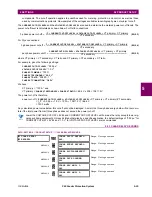
RS485 COM2 RESPONSE MIN TIME
: This setting specifies the minimum time before the rear RS485 port transmits after receiv-
ing data from a host. This feature allows operation with hosts that hold the RS485 transmitter active for some time after
each transmission.
c) ETHERNET NETWORK TOPOLOGY
The F60 has three Ethernet ports. Each Ethernet port must belong to a different network or subnetwork. Configure the IP
address and subnet to ensure that each port meets this requirement. Two subnets are different when the bitwise AND oper-
ation performed between their respective IP address and mask produces a different result. Communication becomes
unpredictable when more than one port is configured to the same subnet.
Example 1
IP1/Mask1: 10.1.1.2/255.255.255.0 (where LAN 1 is 10.1.1.x/255.255.255.0)
IP2/Mask2: 10.2.1.2/255.255.255.0 (where LAN2 is 10.2.1.x/255.255.255.0)
IP3/Mask3: 10.3.1.2/255.255.255.0 (where LAN3 is 10.3.1.x/255.255.255.0)
Example 2
IP1/Mask1: 10.1.1.2/255.0.0.0 (where LAN1 is 10.x.x.x/255.0.0.0)
IP2/Mask2: 11.1.1.2/255.0.0.0 (where LAN2 is 11.x.x.x/255.0.0.0)
IP3/Mask3: 12.1.1.2/255.0.0.0 (where LAN3 is 12.x.x.x/255.0.0.0)
Example 3 — Incorrect
IP1/Mask1: 10.1.1.2/255.0.0.0
IP2/Mask2: 10.2.1.2/255.0.0.0
IP3/Mask3: 10.3.1.2/255.0.0.0
This example is incorrect because the mask of 255.0.0.0 used for the three IP addresses makes them belong to the same
network of 10.x.x.x.
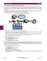
Single LAN, No Redundancy
The topology shown in the following figure allows communications to SCADA, local configuration/monitoring through
EnerVista, and access to the public network shared on the same LAN. No redundancy is provided.
Figure 5–4: NETWORK CONFIGURATION FOR SINGLE LAN
EnerVista Software
ML3000
Public Network
SCADA
UR
P2
P3
LAN1
P1
IP1/
MAC1
859708A2.vsd
Summary of Contents for F60
Page 10: ...x F60 Feeder Protection System GE Multilin TABLE OF CONTENTS ...
Page 30: ...1 20 F60 Feeder Protection System GE Multilin 1 5 USING THE RELAY 1 GETTING STARTED 1 ...
Page 138: ...4 28 F60 Feeder Protection System GE Multilin 4 2 FACEPLATE INTERFACE 4 HUMAN INTERFACES 4 ...
Page 454: ...5 316 F60 Feeder Protection System GE Multilin 5 10 TESTING 5 SETTINGS 5 ...
Page 500: ...7 14 F60 Feeder Protection System GE Multilin 7 1 COMMANDS 7 COMMANDS AND TARGETS 7 ...
Page 508: ...8 8 F60 Feeder Protection System GE Multilin 8 2 FAULT LOCATOR 8 THEORY OF OPERATION 8 ...
Page 522: ...10 12 F60 Feeder Protection System GE Multilin 10 6 DISPOSAL 10 MAINTENANCE 10 ...
Page 660: ...B 116 F60 Feeder Protection System GE Multilin B 4 MEMORY MAPPING APPENDIX B B ...
Page 706: ...E 10 F60 Feeder Protection System GE Multilin E 1 IEC 60870 5 104 APPENDIX E E ...
Page 718: ...F 12 F60 Feeder Protection System GE Multilin F 2 DNP POINT LISTS APPENDIX F F ...
Page 728: ...H 8 F60 Feeder Protection System GE Multilin H 2 ABBREVIATIONS APPENDIX H H Z Impedance Zone ...
Page 730: ...H 10 F60 Feeder Protection System GE Multilin H 3 WARRANTY APPENDIX H H ...


