


5-166
F60 Feeder Protection System
GE Multilin
5.5 FLEXLOGIC
5 SETTINGS
5
The
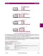
FLEXELEMENT 1 HYSTERESIS
setting defines the pickup–dropout relation of the element by specifying the width of the
hysteresis loop as a percentage of the pickup value as shown in the
FlexElement direction, pickup, and hysteresis
diagram.
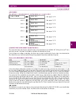
The
FLEXELEMENT 1 DT UNIT
setting specifies the time unit for the setting
FLEXELEMENT 1 dt
. This setting is applicable only if
FLEXELEMENT 1 COMP MODE
is set to “Delta”. The
FLEXELEMENT 1 DT
setting specifies duration of the time interval for the
rate of change mode of operation. This setting is applicable only if
FLEXELEMENT 1 COMP MODE
is set to “Delta”.
This
FLEXELEMENT 1 PKP DELAY
setting specifies the pickup delay of the element. The
FLEXELEMENT 1 RST DELAY
setting
specifies the reset delay of the element.
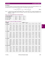
PHASE ANGLE
ϕ
BASE
= 360 degrees (see the UR angle referencing convention)
POWER FACTOR
PF
BASE
= 1.00
RTDs
BASE = 100°C
SENSITIVE DIR POWER
(Sns Dir Power)
P
BASE
= maximum value of 3
×
V
BASE
×
I
BASE
for the +IN and –IN inputs of the sources
configured for the sensitive power directional element(s).
SOURCE CURRENT
I
BASE
= maximum nominal primary RMS value of the +IN and –IN inputs
SOURCE ENERGY
(Positive and Negative Watthours,
Positive and Negative Varhours)
E
BASE
= 10000 MWh or MVAh, respectively
SOURCE POWER
P
BASE
= maximum value of V
BASE
×
I
BASE
for the +IN and –IN inputs
SOURCE THD & HARMONICS
BASE = 1%
SOURCE VOLTAGE
V
BASE
= maximum nominal primary RMS value of the +IN and –IN inputs
SYNCHROCHECK
(Max Delta Volts)
V
BASE
= maximum primary RMS value of all the sources related to the +IN and –IN inputs
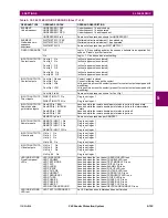
Table 5–21: FLEXELEMENT BASE UNITS
Summary of Contents for F60
Page 10: ...x F60 Feeder Protection System GE Multilin TABLE OF CONTENTS ...
Page 30: ...1 20 F60 Feeder Protection System GE Multilin 1 5 USING THE RELAY 1 GETTING STARTED 1 ...
Page 138: ...4 28 F60 Feeder Protection System GE Multilin 4 2 FACEPLATE INTERFACE 4 HUMAN INTERFACES 4 ...
Page 454: ...5 316 F60 Feeder Protection System GE Multilin 5 10 TESTING 5 SETTINGS 5 ...
Page 500: ...7 14 F60 Feeder Protection System GE Multilin 7 1 COMMANDS 7 COMMANDS AND TARGETS 7 ...
Page 508: ...8 8 F60 Feeder Protection System GE Multilin 8 2 FAULT LOCATOR 8 THEORY OF OPERATION 8 ...
Page 522: ...10 12 F60 Feeder Protection System GE Multilin 10 6 DISPOSAL 10 MAINTENANCE 10 ...
Page 660: ...B 116 F60 Feeder Protection System GE Multilin B 4 MEMORY MAPPING APPENDIX B B ...
Page 706: ...E 10 F60 Feeder Protection System GE Multilin E 1 IEC 60870 5 104 APPENDIX E E ...
Page 718: ...F 12 F60 Feeder Protection System GE Multilin F 2 DNP POINT LISTS APPENDIX F F ...
Page 728: ...H 8 F60 Feeder Protection System GE Multilin H 2 ABBREVIATIONS APPENDIX H H Z Impedance Zone ...
Page 730: ...H 10 F60 Feeder Protection System GE Multilin H 3 WARRANTY APPENDIX H H ...


