


5-288
F60 Feeder Protection System
GE Multilin
5.8 INPUTS/OUTPUTS
5 SETTINGS
5
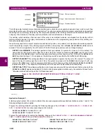
5.8.2 VIRTUAL INPUTS
PATH: SETTINGS
INPUTS/OUTPUTS
VIRTUAL INPUTS
VIRTUAL INPUT 1(64)
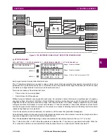
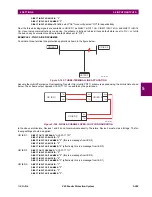
There are 64 virtual inputs that can be individually programmed to respond to input signals from the keypad (via the
COM-
MANDS
menu) and communications protocols. All virtual input operands are defaulted to “Off” (logic 0) unless the appropri-
ate input signal is received.
If the
VIRTUAL INPUT x FUNCTION
is to “Disabled”, the input will be forced to off (logic 0) regardless of any attempt to alter the
input. If set to “Enabled”, the input operates as shown on the logic diagram and generates output FlexLogic operands in
response to received input signals and the applied settings.
There are two types of operation: self-reset and latched. If
VIRTUAL INPUT x TYPE
is “Self-Reset”, when the input signal tran-
sits from off to on, the output operand will be set to on for only one evaluation of the FlexLogic equations and then return to
off. If set to “Latched”, the virtual input sets the state of the output operand to the same state as the most recent received
input.
The self-reset operating mode generates the output operand for a single evaluation of the FlexLogic equations. If
the operand is to be used anywhere other than internally in a FlexLogic equation, it will likely have to be lengthened
in time. A FlexLogic timer with a delayed reset can perform this function.
Figure 5–138: VIRTUAL INPUTS SCHEME LOGIC
VIRTUAL INPUT
1
VIRTUAL INPUT
1
FUNCTION: Disabled
Range: Disabled, Enabled
MESSAGE
VIRTUAL INPUT
1 ID:
Virt Ip 1
Range: Up to 12 alphanumeric characters
MESSAGE
VIRTUAL INPUT
1
TYPE: Latched
Range: Self-Reset, Latched
MESSAGE
VIRTUAL INPUT
1
EVENTS: Disabled
Range: Disabled, Enabled
NOTE
VIRTUAL INPUT 1
FUNCTION:
VIRTUAL INPUT 1 ID:
“Virtual Input 1 to OFF = 0”
“Virtual Input 1 to ON = 1”
AND
AND
AND
OR
SETTING
SETTING
Enabled=1
(Flexlogic Operand)
Virt Ip 1
827080A3.CDR
SETTING
VIRTUAL INPUT 1
TYPE:
Latched
Self - Reset
R
S
Latch
Summary of Contents for F60
Page 10: ...x F60 Feeder Protection System GE Multilin TABLE OF CONTENTS ...
Page 30: ...1 20 F60 Feeder Protection System GE Multilin 1 5 USING THE RELAY 1 GETTING STARTED 1 ...
Page 138: ...4 28 F60 Feeder Protection System GE Multilin 4 2 FACEPLATE INTERFACE 4 HUMAN INTERFACES 4 ...
Page 454: ...5 316 F60 Feeder Protection System GE Multilin 5 10 TESTING 5 SETTINGS 5 ...
Page 500: ...7 14 F60 Feeder Protection System GE Multilin 7 1 COMMANDS 7 COMMANDS AND TARGETS 7 ...
Page 508: ...8 8 F60 Feeder Protection System GE Multilin 8 2 FAULT LOCATOR 8 THEORY OF OPERATION 8 ...
Page 522: ...10 12 F60 Feeder Protection System GE Multilin 10 6 DISPOSAL 10 MAINTENANCE 10 ...
Page 660: ...B 116 F60 Feeder Protection System GE Multilin B 4 MEMORY MAPPING APPENDIX B B ...
Page 706: ...E 10 F60 Feeder Protection System GE Multilin E 1 IEC 60870 5 104 APPENDIX E E ...
Page 718: ...F 12 F60 Feeder Protection System GE Multilin F 2 DNP POINT LISTS APPENDIX F F ...
Page 728: ...H 8 F60 Feeder Protection System GE Multilin H 2 ABBREVIATIONS APPENDIX H H Z Impedance Zone ...
Page 730: ...H 10 F60 Feeder Protection System GE Multilin H 3 WARRANTY APPENDIX H H ...


