


GE Multilin
F60 Feeder Protection System
4-13
4 HUMAN INTERFACES
4.2 FACEPLATE INTERFACE
4
4.2FACEPLATE INTERFACE
4.2.1 FACEPLATE
a) ENHANCED FACEPLATE
The front panel interface is one of two supported interfaces, the other interface being EnerVista UR Setup software. The
front panel interface consists of LED panels, an RS232 port, keypad, LCD display, control pushbuttons, and optional user-
programmable pushbuttons.
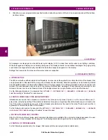
The faceplate is hinged to allow easy access to the removable modules.
Figure 4–15: UR-SERIES ENHANCED FACEPLATE
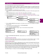
b) STANDARD FACEPLATE
There are two interfaces: the front panel and the EnerVista UR Setup software. The front panel interface consists of LED
panels, an RS232 port, keypad, LCD display, control pushbuttons, and optional user-programmable pushbuttons.
The faceplate is hinged to allow easy access to the removable modules. There is also a removable dust cover that fits over
the faceplate that must be removed in order to access the keypad panel. The following figure shows the horizontal arrange-
ment of the faceplate panels.
Figure 4–16: UR-SERIES STANDARD HORIZONTAL FACEPLATE PANELS
Five column LED indicator panel
Display
User-programmable pushbuttons 1 to 16
842810A2.CDR
Keypad
Front panel
RS232 port
Control
pushbuttons (3)
LED panel 1
LED panel 2
Display
User-programmable
pushbuttons 1 to 12
Keypad
Front panel
RS232 port
Small user-programmable
(control) pushbuttons 1 to 7
LED panel 3
827801A9.CDR
Summary of Contents for F60
Page 10: ...x F60 Feeder Protection System GE Multilin TABLE OF CONTENTS ...
Page 30: ...1 20 F60 Feeder Protection System GE Multilin 1 5 USING THE RELAY 1 GETTING STARTED 1 ...
Page 138: ...4 28 F60 Feeder Protection System GE Multilin 4 2 FACEPLATE INTERFACE 4 HUMAN INTERFACES 4 ...
Page 454: ...5 316 F60 Feeder Protection System GE Multilin 5 10 TESTING 5 SETTINGS 5 ...
Page 500: ...7 14 F60 Feeder Protection System GE Multilin 7 1 COMMANDS 7 COMMANDS AND TARGETS 7 ...
Page 508: ...8 8 F60 Feeder Protection System GE Multilin 8 2 FAULT LOCATOR 8 THEORY OF OPERATION 8 ...
Page 522: ...10 12 F60 Feeder Protection System GE Multilin 10 6 DISPOSAL 10 MAINTENANCE 10 ...
Page 660: ...B 116 F60 Feeder Protection System GE Multilin B 4 MEMORY MAPPING APPENDIX B B ...
Page 706: ...E 10 F60 Feeder Protection System GE Multilin E 1 IEC 60870 5 104 APPENDIX E E ...
Page 718: ...F 12 F60 Feeder Protection System GE Multilin F 2 DNP POINT LISTS APPENDIX F F ...
Page 728: ...H 8 F60 Feeder Protection System GE Multilin H 2 ABBREVIATIONS APPENDIX H H Z Impedance Zone ...
Page 730: ...H 10 F60 Feeder Protection System GE Multilin H 3 WARRANTY APPENDIX H H ...


