


4-18
F60 Feeder Protection System
GE Multilin
4.2 FACEPLATE INTERFACE
4 HUMAN INTERFACES
4
•
The F60 front panel label cutout sheet (GE Multilin part number 1006-0047) has been downloaded from
http://www.gegridsolutions.com/products/support/ur/URLEDenhanced.doc
and printed
•
Small-bladed knife
To create custom LED labels for the enhanced front panel display:
1.
Start the EnerVista UR Setup software.
2.
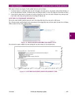
Select the
Front Panel Report
item at the bottom of the menu tree for the settings file. The front panel report window
displays.
Figure 4–22: FRONT PANEL REPORT WINDOW
3.
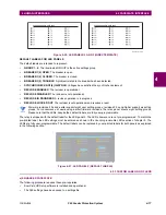
Enter the text to appear next to each LED and above each user-programmable pushbuttons in the fields provided.
4.
Feed the F60 front panel label cutout sheet into a printer and press the
button in the front panel report window.
5.
When printing is complete, fold the sheet along the perforated lines and punch out the labels.
6.
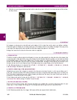
Remove the F60 label insert tool from the package and bend the tabs as described in the following procedures. These
tabs are used for removal of the default and custom LED labels.
It is important that the tool be used EXACTLY as shown below, with the printed side containing the GE part number
facing the user.
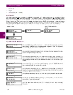
The label package shipped with every F60 contains the three default labels shown below, the custom label template sheet,
and the label removal tool.
If the default labels are suitable for your application, insert them in the appropriate slots and program the LEDs to match
them. If you require custom labels, follow the procedures below to remove the original labels and insert the new ones.
The following procedure describes how to setup and use the label removal tool.
NOTE
Summary of Contents for F60
Page 10: ...x F60 Feeder Protection System GE Multilin TABLE OF CONTENTS ...
Page 30: ...1 20 F60 Feeder Protection System GE Multilin 1 5 USING THE RELAY 1 GETTING STARTED 1 ...
Page 138: ...4 28 F60 Feeder Protection System GE Multilin 4 2 FACEPLATE INTERFACE 4 HUMAN INTERFACES 4 ...
Page 454: ...5 316 F60 Feeder Protection System GE Multilin 5 10 TESTING 5 SETTINGS 5 ...
Page 500: ...7 14 F60 Feeder Protection System GE Multilin 7 1 COMMANDS 7 COMMANDS AND TARGETS 7 ...
Page 508: ...8 8 F60 Feeder Protection System GE Multilin 8 2 FAULT LOCATOR 8 THEORY OF OPERATION 8 ...
Page 522: ...10 12 F60 Feeder Protection System GE Multilin 10 6 DISPOSAL 10 MAINTENANCE 10 ...
Page 660: ...B 116 F60 Feeder Protection System GE Multilin B 4 MEMORY MAPPING APPENDIX B B ...
Page 706: ...E 10 F60 Feeder Protection System GE Multilin E 1 IEC 60870 5 104 APPENDIX E E ...
Page 718: ...F 12 F60 Feeder Protection System GE Multilin F 2 DNP POINT LISTS APPENDIX F F ...
Page 728: ...H 8 F60 Feeder Protection System GE Multilin H 2 ABBREVIATIONS APPENDIX H H Z Impedance Zone ...
Page 730: ...H 10 F60 Feeder Protection System GE Multilin H 3 WARRANTY APPENDIX H H ...


