


5-44
F60 Feeder Protection System
GE Multilin
5.2 PRODUCT SETUP
5 SETTINGS
5
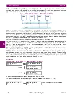
The configurable GOOSE settings are shown below.
PATH: SETTINGS
PRODUCT SETUP
COMMUNICATIONS
IEC 61850 PROTOCOL
GSSE/GOOSE CONFIGURATION
TRANSMISSION
CONFIGURABLE GOOSE
CONFIGURABLE GOOSE 1(8)
The configurable GOOSE settings allow the F60 to be configured to transmit a number of different datasets within IEC
61850 GOOSE messages. Up to eight different configurable datasets can be configured and transmitted. This is useful for
intercommunication between F60 IEDs and devices from other manufacturers that support IEC 61850.
The configurable GOOSE feature allows for the configuration of the datasets to be transmitted or received from the F60.
The F60 supports the configuration of eight (8) transmission and reception datasets, allowing for the optimization of data
transfer between devices.
Items programmed for dataset 1 and 2 will have changes in their status transmitted as soon as the change is detected.
Datasets 1 and 2 should be used for high-speed transmission of data that is required for applications such as transfer trip-
ping, blocking, and breaker fail initiate. At least one digital status value needs to be configured in the required dataset to
enable transmission of configured data. Configuring analog data only to dataset 1 or 2 will not activate transmission.
Items programmed for datasets 3 through 8 will have changes in their status transmitted at a maximum rate of every
100 ms. Datasets 3 through 8 will regularly analyze each data item configured within them every 100 ms to identify if any
changes have been made. If any changes in the data items are detected, these changes will be transmitted through a
GOOSE message. If there are no changes detected during this 100 ms period, no GOOSE message will be sent.
For all datasets 1 through 8, the integrity GOOSE message will still continue to be sent at the pre-configured rate even if no
changes in the data items are detected.
The GOOSE functionality was enhanced to prevent the relay from flooding a communications network with GOOSE mes-
sages due to an oscillation being created that is triggering a message.
The F60 has the ability of detecting if a data item in one of the GOOSE datasets is erroneously oscillating. This can be
caused by events such as errors in logic programming, inputs improperly being asserted and de-asserted, or failed station
components. If erroneously oscillation is detected, the F60 will stop sending GOOSE messages from the dataset for a min-
imum period of one second. Should the oscillation persist after the one second time-out period, the F60 will continue to
block transmission of the dataset. The F60 will assert the
MAINTENANCE ALERT: GGIO Ind XXX oscill
self-test error mes-
sage on the front panel display, where
XXX
denotes the data item detected as oscillating.
For versions 5.70 and higher, the F60 supports four retransmission schemes: aggressive, medium, relaxed, and heartbeat.
The aggressive scheme is only supported in fast type 1A GOOSE messages (GOOSEOut 1 and GOOSEOut 2). For slow
GOOSE messages (GOOSEOut 3 to GOOSEOut 8) the aggressive scheme is the same as the medium scheme.
CONFIGURABLE
GOOSE 1
CONFIG GSE 1
FUNCTION: Enabled
Range: Enabled, Disabled
MESSAGE
CONFIG GSE 1 ID:
GOOSEOut_1
Range: 65-character ASCII string
MESSAGE
CONFIG GSE 1 DST MAC:
000000000000
Range: standard MAC address
MESSAGE
CONFIG GSE 1
VLAN PRIORITY: 4
Range: 0 to 7 in steps of 1
MESSAGE
CONFIG GSE 1
VLAN ID:
0
Range: 0 to 4095 in steps of 1
MESSAGE
CONFIG GSE 1
ETYPE APPID:
0
Range: 0 to 16383 in steps of 1
MESSAGE
CONFIG GSE 1
CONFREV:
1
Range: 0 to 4294967295 in steps of 1
MESSAGE
CONFIG GSE 1 RESTRANS
CURVE: Relaxed
Range: Aggressive, Medium, Relaxed, Heartbeat
MESSAGE
CONFIG GSE 1
DATASET ITEMS
Range: 64 data items; each can be set to all valid MMS
data item references for transmitted data
Summary of Contents for F60
Page 10: ...x F60 Feeder Protection System GE Multilin TABLE OF CONTENTS ...
Page 30: ...1 20 F60 Feeder Protection System GE Multilin 1 5 USING THE RELAY 1 GETTING STARTED 1 ...
Page 138: ...4 28 F60 Feeder Protection System GE Multilin 4 2 FACEPLATE INTERFACE 4 HUMAN INTERFACES 4 ...
Page 454: ...5 316 F60 Feeder Protection System GE Multilin 5 10 TESTING 5 SETTINGS 5 ...
Page 500: ...7 14 F60 Feeder Protection System GE Multilin 7 1 COMMANDS 7 COMMANDS AND TARGETS 7 ...
Page 508: ...8 8 F60 Feeder Protection System GE Multilin 8 2 FAULT LOCATOR 8 THEORY OF OPERATION 8 ...
Page 522: ...10 12 F60 Feeder Protection System GE Multilin 10 6 DISPOSAL 10 MAINTENANCE 10 ...
Page 660: ...B 116 F60 Feeder Protection System GE Multilin B 4 MEMORY MAPPING APPENDIX B B ...
Page 706: ...E 10 F60 Feeder Protection System GE Multilin E 1 IEC 60870 5 104 APPENDIX E E ...
Page 718: ...F 12 F60 Feeder Protection System GE Multilin F 2 DNP POINT LISTS APPENDIX F F ...
Page 728: ...H 8 F60 Feeder Protection System GE Multilin H 2 ABBREVIATIONS APPENDIX H H Z Impedance Zone ...
Page 730: ...H 10 F60 Feeder Protection System GE Multilin H 3 WARRANTY APPENDIX H H ...


