


B-16
F60 Feeder Protection System
GE Multilin
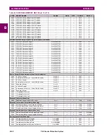
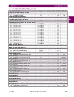
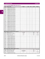
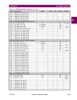
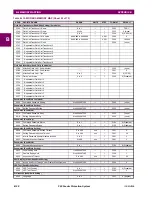
B.4 MEMORY MAPPING
APPENDIX B
B
16C7
...Repeated for Field RTD 8
Field Unit Transducer Actuals (Read Only) (8 modules)
16C8
Field Transducer 1 Value
-32.768 to 32.767
---
0.001
F004
0
16CA
...Repeated for Field Transducer 2
16CC
...Repeated for Field Transducer 3
16CE
...Repeated for Field Transducer 4
16D0
...Repeated for Field Transducer 5
16D2
...Repeated for Field Transducer 6
16D4
...Repeated for Field Transducer 7
16D6
...Repeated for Field Transducer 8
Frequency Rate of Change Actual Values (Read Only) (4 modules)
16E0
Frequency Rate of Change 1
-327.67 to 327.67
Hz/s
0.01
F002
0
16E1
Reserved (3 items)
0 to 65535
---
1
F001
0
16E4
...Repeated for Frequency Rate of Change 2
16E8
...Repeated for Frequency Rate of Change 3
16EC
...Repeated for Frequency Rate of Change 4
Source Current (Read Only) (4 modules)
1800
Source 1 Phase A Current RMS
0 to 999999.999
A
0.001
F060
0
1802
Source 1 Phase B Current RMS
0 to 999999.999
A
0.001
F060
0
1804
Source 1 Phase C Current RMS
0 to 999999.999
A
0.001
F060
0
1806
Source 1 Neutral Current RMS
0 to 999999.999
A
0.001
F060
0
1808
Source 1 Phase A Current Magnitude
0 to 999999.999
A
0.001
F060
0
180A
Source 1 Phase A Current Angle
-359.9 to 0
degrees
0.1
F002
0
180B
Source 1 Phase B Current Magnitude
0 to 999999.999
A
0.001
F060
0
180D
Source 1 Phase B Current Angle
-359.9 to 0
degrees
0.1
F002
0
180E
Source 1 Phase C Current Magnitude
0 to 999999.999
A
0.001
F060
0
1810
Source 1 Phase C Current Angle
-359.9 to 0
degrees
0.1
F002
0
1811
Source 1 Neutral Current Magnitude
0 to 999999.999
A
0.001
F060
0
1813
Source 1 Neutral Current Angle
-359.9 to 0
degrees
0.1
F002
0
1814
Source 1 Ground Current RMS
0 to 999999.999
A
0.001
F060
0
1816
Source 1 Ground Current Magnitude
0 to 999999.999
A
0.001
F060
0
1818
Source 1 Ground Current Angle
-359.9 to 0
degrees
0.1
F002
0
1819
Source 1 Zero Sequence Current Magnitude
0 to 999999.999
A
0.001
F060
0
181B
Source 1 Zero Sequence Current Angle
-359.9 to 0
degrees
0.1
F002
0
181C
Source 1 Positive Sequence Current Magnitude
0 to 999999.999
A
0.001
F060
0
181E
Source 1 Positive Sequence Current Angle
-359.9 to 0
degrees
0.1
F002
0
181F
Source 1 Negative Sequence Current Magnitude
0 to 999999.999
A
0.001
F060
0
1821
Source 1 Negative Sequence Current Angle
-359.9 to 0
degrees
0.1
F002
0
1822
Source 1 Differential Ground Current Magnitude
0 to 999999.999
A
0.001
F060
0
1824
Source 1 Differential Ground Current Angle
-359.9 to 0
degrees
0.1
F002
0
1825
Reserved (27 items)
---
---
---
F001
0
1840
...Repeated for Source 2
1880
...Repeated for Source 3
18C0
...Repeated for Source 4
Source Voltage (Read Only) (4 modules)
1A00
Source 1 Phase AG Voltage RMS
0 to 999999.999
V
0.001
F060
0
1A02
Source 1 Phase BG Voltage RMS
0 to 999999.999
V
0.001
F060
0
1A04
Source 1 Phase CG Voltage RMS
0 to 999999.999
V
0.001
F060
0
1A06
Source 1 Phase AG Voltage Magnitude
0 to 999999.999
V
0.001
F060
0
1A08
Source 1 Phase AG Voltage Angle
-359.9 to 0
degrees
0.1
F002
0
1A09
Source 1 Phase BG Voltage Magnitude
0 to 999999.999
V
0.001
F060
0
1A0B
Source 1 Phase BG Voltage Angle
-359.9 to 0
degrees
0.1
F002
0
1A0C
Source 1 Phase CG Voltage Magnitude
0 to 999999.999
V
0.001
F060
0
1A0E
Source 1 Phase CG Voltage Angle
-359.9 to 0
degrees
0.1
F002
0
Table B–10: MODBUS MEMORY MAP (Sheet 8 of 70)
ADDR
REGISTER NAME
RANGE
UNITS
STEP
FORMAT
DEFAULT
Summary of Contents for F60
Page 10: ...x F60 Feeder Protection System GE Multilin TABLE OF CONTENTS ...
Page 30: ...1 20 F60 Feeder Protection System GE Multilin 1 5 USING THE RELAY 1 GETTING STARTED 1 ...
Page 138: ...4 28 F60 Feeder Protection System GE Multilin 4 2 FACEPLATE INTERFACE 4 HUMAN INTERFACES 4 ...
Page 454: ...5 316 F60 Feeder Protection System GE Multilin 5 10 TESTING 5 SETTINGS 5 ...
Page 500: ...7 14 F60 Feeder Protection System GE Multilin 7 1 COMMANDS 7 COMMANDS AND TARGETS 7 ...
Page 508: ...8 8 F60 Feeder Protection System GE Multilin 8 2 FAULT LOCATOR 8 THEORY OF OPERATION 8 ...
Page 522: ...10 12 F60 Feeder Protection System GE Multilin 10 6 DISPOSAL 10 MAINTENANCE 10 ...
Page 660: ...B 116 F60 Feeder Protection System GE Multilin B 4 MEMORY MAPPING APPENDIX B B ...
Page 706: ...E 10 F60 Feeder Protection System GE Multilin E 1 IEC 60870 5 104 APPENDIX E E ...
Page 718: ...F 12 F60 Feeder Protection System GE Multilin F 2 DNP POINT LISTS APPENDIX F F ...
Page 728: ...H 8 F60 Feeder Protection System GE Multilin H 2 ABBREVIATIONS APPENDIX H H Z Impedance Zone ...
Page 730: ...H 10 F60 Feeder Protection System GE Multilin H 3 WARRANTY APPENDIX H H ...


