


2-20
F60 Feeder Protection System
GE Multilin
2.4 SPECIFICATIONS
2 PRODUCT DESCRIPTION
2
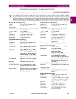
PHASE DIRECTIONAL OVERCURRENT
Relay connection:
90
°
(quadrature)
Quadrature voltage:
ABC phase seq.: phase A (V
BC
), phase
B (V
CA
), phase C (V
AB
); ACB phase
seq.: phase A (V
CB
), phase B (V
AC
),
phase C (V
BA
)
Polarizing voltage threshold: 0.000 to 3.000 pu in steps of 0.001
Current sensitivity threshold: 0.05 pu
Characteristic angle:
0 to 359
°
in steps of 1
Angle accuracy:
±2°
Operation time (FlexLogic operands):
Tripping (reverse load, forward fault):
<
12 ms, typically
Blocking (forward load, reverse fault):
<
8 ms, typically
NEUTRAL DIRECTIONAL OVERCURRENT
Directionality:
Co-existing forward and reverse
Polarizing:
Voltage, Current, Dual, Dual-V, Dual-I
Polarizing voltage:
V_0 or VX
Polarizing current:
IG
Operating current:
I_0
Level sensing:
3
×
(|I_0| –
K
×
|I_1|), IG
Restraint,
K
:
0.000 to 0.500 in steps of 0.001
Characteristic angle:
–90 to 90° in steps of 1
Limit angle:
40 to 90° in steps of 1, independent for
forward and reverse
Angle accuracy:
±2°
Offset impedance:
0.00 to 250.00
Ω
in steps of 0.01
Pickup level:
0.002 to 30.000 pu in steps of 0.01
Dropout level:
97 to 98%
Operation time:
<16 ms at 3
×
pickup at 60 Hz
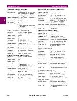
NEGATIVE SEQUENCE DIRECTIONAL OC
Directionality:
Co-existing forward and reverse
Polarizing:
Voltage
Polarizing voltage:
V_2
Operating current:
I_2
Level sensing:
Zero-sequence:|I_0| –
K
×
|I_1|
Negative-sequence:|I_2| –
K
×
|I_1|
Restraint,
K
:
0.000 to 0.500 in steps of 0.001
Characteristic angle:
0 to 90° in steps of 1
Limit angle:
40 to 90° in steps of 1, independent for
forward and reverse
Angle accuracy:
±2°
Offset impedance:
0.00 to 250.00
Ω
in steps of 0.01
Pickup level:
0.015 to 30.000 pu in steps of 0.01
Dropout level:
97 to 98%
Operation time:
<16 ms at 3
×
pickup at 60 Hz
WATTMETRIC ZERO-SEQUENCE DIRECTIONAL
Measured power:
zero-sequence
Number of elements:
2
Characteristic angle:
0 to 360° in steps of 1
Minimum power:
0.001 to 1.200 pu in steps of 0.001
Pickup level accuracy:
±1% or ±0.0025 pu, whichever is greater
Hysteresis:
3% or 0.001 pu, whichever is greater
Pickup delay:
definite time (0 to 600.00 s in steps of
0.01), inverse time, or FlexCurve
Inverse time multiplier:
0.01 to 2.00 s in steps of 0.01
Curve timing accuracy: ±3.5% of operate time or ±1 cycle
(whichever is greater) from pickup to
operate
Operate time:
<30 ms at 60 Hz
SENSITIVE DIRECTIONAL POWER
Measured power:
3-phase, true RMS
Number of stages:
2
Characteristic angle:
0 to 359° in steps of 1
Calibration angle:
0.00 to 0.95° in steps of 0.05
Minimum power:
–1.200 to 1.200 pu in steps of 0.001
Pickup level accuracy:
±1% or ±0.001 pu, whichever is greater
Hysteresis:
2% or 0.001 pu, whichever is greater
Pickup delay:
0 to 600.00 s in steps of 0.01
Timer accuracy:
±3% of operate time or ±1/4 cycle
(whichever is greater)
Operate time:
<50 ms
PHASE UNDERVOLTAGE
Voltage:
Phasor only
Pickup level:
0.000 to 3.000 pu in steps of 0.001
Dropout level:
102 to 103% of pickup
Level accuracy:
±0.5% of reading from 10 to 208 V
Curve shapes:
GE IAV Inverse;
Definite Time (0.1s base curve)
Curve multiplier:
Time dial = 0.00 to 600.00 in steps of
0.01
Curve timing accuracy
at <0.90 x pickup:
±3.5% of operate time or ±1/2 cycle
(whichever is greater) from pickup to
operate
Operate time:
<30 ms at 0.9 pickup at 60 Hz for Defi-
nite Time mode
AUXILIARY UNDERVOLTAGE
Pickup level:
0.000 to 3.000 pu in steps of 0.001
Dropout level:
102 to 103% of pickup
Level accuracy:
±0.5% of reading from 10 to 208 V
Curve shapes:
GE IAV Inverse, Definite Time
Curve multiplier:
Time Dial = 0 to 600.00 in steps of 0.01
Curve timing accuracy
at <0.90 x pickup:
±3.5% of operate time or ±1/2 cycle
(whichever is greater) from pickup to
operate
Operate time:
<30 ms at 0.9 pickup at 60 Hz for Defi-
nite Time mode
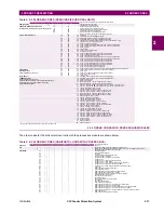
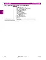
Summary of Contents for F60
Page 10: ...x F60 Feeder Protection System GE Multilin TABLE OF CONTENTS ...
Page 30: ...1 20 F60 Feeder Protection System GE Multilin 1 5 USING THE RELAY 1 GETTING STARTED 1 ...
Page 138: ...4 28 F60 Feeder Protection System GE Multilin 4 2 FACEPLATE INTERFACE 4 HUMAN INTERFACES 4 ...
Page 454: ...5 316 F60 Feeder Protection System GE Multilin 5 10 TESTING 5 SETTINGS 5 ...
Page 500: ...7 14 F60 Feeder Protection System GE Multilin 7 1 COMMANDS 7 COMMANDS AND TARGETS 7 ...
Page 508: ...8 8 F60 Feeder Protection System GE Multilin 8 2 FAULT LOCATOR 8 THEORY OF OPERATION 8 ...
Page 522: ...10 12 F60 Feeder Protection System GE Multilin 10 6 DISPOSAL 10 MAINTENANCE 10 ...
Page 660: ...B 116 F60 Feeder Protection System GE Multilin B 4 MEMORY MAPPING APPENDIX B B ...
Page 706: ...E 10 F60 Feeder Protection System GE Multilin E 1 IEC 60870 5 104 APPENDIX E E ...
Page 718: ...F 12 F60 Feeder Protection System GE Multilin F 2 DNP POINT LISTS APPENDIX F F ...
Page 728: ...H 8 F60 Feeder Protection System GE Multilin H 2 ABBREVIATIONS APPENDIX H H Z Impedance Zone ...
Page 730: ...H 10 F60 Feeder Protection System GE Multilin H 3 WARRANTY APPENDIX H H ...


