


GE Multilin
F60 Feeder Protection System
5-283
5 SETTINGS
5.7 CONTROL ELEMENTS
5
(EQ 5.35)
When current is less than the dropout level,
I
n
> 0.97 ×
k
×
I
B
, the element starts decreasing the thermal energy:
(EQ 5.36)
In the above equations,
•
∆
t
is the power cycle duration
•
n
is the power cycle index
•
t
op
(
In
)
is the trip time calculated at index
n
as per the IEC255-8 cold curve or hot curve equations
•
t
rst
(
In
)
is the reset time calculated at index
n
as per the reset time equation
•
I
n
is the measured overload RMS current at index
n
•
E
n
is the accumulated energy at index
n
•
E
n
– 1
is the accumulated energy at index
n
– 1
The thermal overload protection element removes the
THERMAL PROT 1 OP
output operand when
E
< 0.05. In case of
emergency, the thermal memory and
THERMAL PROT 1 OP
output operand can be reset using
THERM PROT 1 RESET
setting.
All calculations are performed per phase. If the accumulated energy reaches value 1 in any phase, the thermal overload
protection element operates and only resets when energy is less than 0.05 in all three phases.
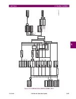
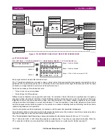
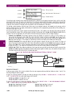
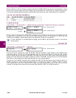
The logic for the thermal overload protection element is shown below.
Figure 5–134: THERMAL OVERLOAD PROTECTION SCHEME LOGIC
Table 5–37: TYPICAL TIME CONSTANTS
PROTECTED EQUIPMENT
TIME CONSTANT
MINIMUM RESET TIME
Capacitor bank
10 minutes
30 minutes
Overhead line
10 minutes
20 minutes
Air-core reactor
40 minutes
30 minutes
Busbar
60 minutes
20 minutes
Underground cable
20 to 60 minutes
60 minutes
E
n
E
n
1
–
t
Δ
t
op In
( )
---------------
+
=
E
n
E
n
1
–
t
Δ
t
rst In
( )
---------------
–
=
SETTINGS
Enabled = 1
Function
Off = 0
Block
AND
SETTING
IA RMS
Source
IB RMS
IC RMS
SETTINGS
IA > k × Ib
K Factor
IB > k × Ib
IC > k × Ic
Base Current
OR
AND
SETTING
Trip Time Constant
RUN
E > 0.1
SETTINGS
Reset Time Constant
RUN
E < 0.1
Minimum Reset Time
Reset E to 0
SETTING
Off = 0
Reset
Latch
S
R
Reset-dominant
FLEXLOGIC OPERAND
THERMAL PROT 1 OP
FLEXLOGIC OPERAND
THERMAL PROT 1 PKP
827013A1.CDR
Summary of Contents for F60
Page 10: ...x F60 Feeder Protection System GE Multilin TABLE OF CONTENTS ...
Page 30: ...1 20 F60 Feeder Protection System GE Multilin 1 5 USING THE RELAY 1 GETTING STARTED 1 ...
Page 138: ...4 28 F60 Feeder Protection System GE Multilin 4 2 FACEPLATE INTERFACE 4 HUMAN INTERFACES 4 ...
Page 454: ...5 316 F60 Feeder Protection System GE Multilin 5 10 TESTING 5 SETTINGS 5 ...
Page 500: ...7 14 F60 Feeder Protection System GE Multilin 7 1 COMMANDS 7 COMMANDS AND TARGETS 7 ...
Page 508: ...8 8 F60 Feeder Protection System GE Multilin 8 2 FAULT LOCATOR 8 THEORY OF OPERATION 8 ...
Page 522: ...10 12 F60 Feeder Protection System GE Multilin 10 6 DISPOSAL 10 MAINTENANCE 10 ...
Page 660: ...B 116 F60 Feeder Protection System GE Multilin B 4 MEMORY MAPPING APPENDIX B B ...
Page 706: ...E 10 F60 Feeder Protection System GE Multilin E 1 IEC 60870 5 104 APPENDIX E E ...
Page 718: ...F 12 F60 Feeder Protection System GE Multilin F 2 DNP POINT LISTS APPENDIX F F ...
Page 728: ...H 8 F60 Feeder Protection System GE Multilin H 2 ABBREVIATIONS APPENDIX H H Z Impedance Zone ...
Page 730: ...H 10 F60 Feeder Protection System GE Multilin H 3 WARRANTY APPENDIX H H ...


