


5-104
F60 Feeder Protection System
GE Multilin
5.4 SYSTEM SETUP
5 SETTINGS
5
The approach used to configure the AC sources consists of several steps; first step is to specify the information about each
CT and VT input. For CT inputs, this is the nominal primary and secondary current. For VTs, this is the connection type,
ratio and nominal secondary voltage. Once the inputs have been specified, the configuration for each source is entered,
including specifying which CTs are summed together.
When the F60 is equipped with a type 8Z CT/VT module for high impedance fault detection, the CT bank of this
module should not be assigned to a source which will be used by any conventional protection element. The type 8Z
module CT bank is used solely by the high impedance fault detection algorithm.
User selection of AC parameters for comparator elements:
CT/VT modules automatically calculate all current and voltage parameters from the available inputs. Users must select the
specific input parameters to be measured by every element in the relevant settings menu. The internal design of the ele-
ment specifies which type of parameter to use and provides a setting for source selection. In elements where the parameter
may be either fundamental or RMS magnitude, such as phase time overcurrent, two settings are provided. One setting
specifies the source, the second setting selects between fundamental phasor and RMS.
AC input actual values:
The calculated parameters associated with the configured voltage and current inputs are displayed in the current and volt-
age sections of actual values. Only the phasor quantities associated with the actual AC physical input channels will be dis-
played here. All parameters contained within a configured source are displayed in the sources section of the actual values.
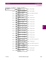
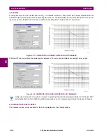
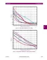
DISTURBANCE DETECTORS (INTERNAL):
The disturbance detector (ANSI 50DD) element is a sensitive current disturbance detector that detects any disturbance on
the protected system. The 50DD function is used directly in some elements in the relay, for example VT Fuse Failure detec-
tor or Fault Report. It can also be used to supervise current-based elements to prevent maloperation as a result of the
wrong settings or external CT wiring problem. A disturbance detector is provided for each source.
The 50DD function responds to the changes in magnitude of the sequence currents. The disturbance detector scheme
logic is as follows:
NOTE
Summary of Contents for F60
Page 10: ...x F60 Feeder Protection System GE Multilin TABLE OF CONTENTS ...
Page 30: ...1 20 F60 Feeder Protection System GE Multilin 1 5 USING THE RELAY 1 GETTING STARTED 1 ...
Page 138: ...4 28 F60 Feeder Protection System GE Multilin 4 2 FACEPLATE INTERFACE 4 HUMAN INTERFACES 4 ...
Page 454: ...5 316 F60 Feeder Protection System GE Multilin 5 10 TESTING 5 SETTINGS 5 ...
Page 500: ...7 14 F60 Feeder Protection System GE Multilin 7 1 COMMANDS 7 COMMANDS AND TARGETS 7 ...
Page 508: ...8 8 F60 Feeder Protection System GE Multilin 8 2 FAULT LOCATOR 8 THEORY OF OPERATION 8 ...
Page 522: ...10 12 F60 Feeder Protection System GE Multilin 10 6 DISPOSAL 10 MAINTENANCE 10 ...
Page 660: ...B 116 F60 Feeder Protection System GE Multilin B 4 MEMORY MAPPING APPENDIX B B ...
Page 706: ...E 10 F60 Feeder Protection System GE Multilin E 1 IEC 60870 5 104 APPENDIX E E ...
Page 718: ...F 12 F60 Feeder Protection System GE Multilin F 2 DNP POINT LISTS APPENDIX F F ...
Page 728: ...H 8 F60 Feeder Protection System GE Multilin H 2 ABBREVIATIONS APPENDIX H H Z Impedance Zone ...
Page 730: ...H 10 F60 Feeder Protection System GE Multilin H 3 WARRANTY APPENDIX H H ...


