


GE Multilin
F60 Feeder Protection System
5-235
5 SETTINGS
5.7 CONTROL ELEMENTS
5
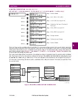
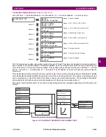
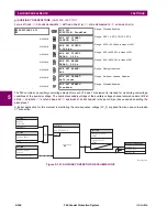
The following figures illustrate the operation of the selector switch. In these diagrams, “T” represents a time-out setting.
Figure 5–108: TIME-OUT MODE
842737A1.CDR
STEP-UP
3BIT A0
3BIT A1
3BIT A2
POS 1
POS 2
POS 3
POS 4
POS 5
POS 6
POS 7
BIT 0
BIT 1
BIT 2
pre-existing
position 2
changed to 4 with
a pushbutton
changed to 1 with
a 3-bit input
changed to 2 with a
pushbutton
T
T
T
T
changed to 7 with
a 3-bit input
STP ALARM
BIT ALARM
ALARM
Summary of Contents for F60
Page 10: ...x F60 Feeder Protection System GE Multilin TABLE OF CONTENTS ...
Page 30: ...1 20 F60 Feeder Protection System GE Multilin 1 5 USING THE RELAY 1 GETTING STARTED 1 ...
Page 138: ...4 28 F60 Feeder Protection System GE Multilin 4 2 FACEPLATE INTERFACE 4 HUMAN INTERFACES 4 ...
Page 454: ...5 316 F60 Feeder Protection System GE Multilin 5 10 TESTING 5 SETTINGS 5 ...
Page 500: ...7 14 F60 Feeder Protection System GE Multilin 7 1 COMMANDS 7 COMMANDS AND TARGETS 7 ...
Page 508: ...8 8 F60 Feeder Protection System GE Multilin 8 2 FAULT LOCATOR 8 THEORY OF OPERATION 8 ...
Page 522: ...10 12 F60 Feeder Protection System GE Multilin 10 6 DISPOSAL 10 MAINTENANCE 10 ...
Page 660: ...B 116 F60 Feeder Protection System GE Multilin B 4 MEMORY MAPPING APPENDIX B B ...
Page 706: ...E 10 F60 Feeder Protection System GE Multilin E 1 IEC 60870 5 104 APPENDIX E E ...
Page 718: ...F 12 F60 Feeder Protection System GE Multilin F 2 DNP POINT LISTS APPENDIX F F ...
Page 728: ...H 8 F60 Feeder Protection System GE Multilin H 2 ABBREVIATIONS APPENDIX H H Z Impedance Zone ...
Page 730: ...H 10 F60 Feeder Protection System GE Multilin H 3 WARRANTY APPENDIX H H ...


