


5-274
F60 Feeder Protection System
GE Multilin
5.7 CONTROL ELEMENTS
5 SETTINGS
5
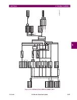
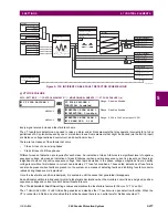
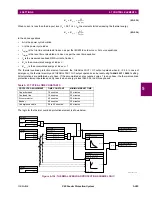
•
BREAKER RESTRIKE 1 HF DETECT
: This setting enables/disables high-frequency (HF) pattern detection when
breaker restrike occurs. High-frequency pattern is typical for capacitor bank, cables, and long transmission line appli-
cations.
•
BRK RSTR 1 BRK OPEN
: This setting assigns a FlexLogic operand indicating the open position of the breaker. It must
be logic “1” when breaker is open. It is important to assign either 52 contact with this setting or breaker close command
with
BRK RSTR 1 CLS CMD
setting to give clear indication to the relay about breaker status.
•
BRK RSTR 1 OPEN CMD
: This setting assigns a FlexLogic operand indicating a breaker open command. It must be
logic “1” when breaker is opened, either manually or from protection logic.
•
BRK RSTR 1 CLS CMD
: This setting assigns a FlexLogic operand indicating a breaker close command. It must be
logic “1” when breaker is closed.
Figure 5–128: BREAKER RESTRIKE SCHEME LOGIC
RUN
Current interruption
detection logic
I
< 0.05 pu
mag
for
t
> ¼ cycle
ARMED
RESET
SETTING
= Enabled
BREAKER RESTRIKE 1
FUNCTION
SETTING
= Off
BKR RSTR 1 BLK
AND
SETTING
= IA
BREAKER RESTRIKE 1
SOURCE
= IB
= IC
SETTING
= Off
BKR RSTR 1 BKR OPEN
SETTING
= Off
BKR RSTR 1 OPEN CMD
SETTING
= Off
BKR RSTR 1 CLS CMD
AND
OR
SETTING
BREAKER RESTRIKE 1 PICKUP
RUN
Restrike detection logic
0
T
RST
SETTING
BREAKER RESTRIKE 1
RESET DELAY
0
T
RST
0
T
RST
FLEXLOGIC OPERANDS
BKR RESTRIKE 1 OP A
BKR RESTRIKE 1 OP B
BKR RESTRIKE 1 OP C
BKR RESTRIKE 1 OP
FLEXLOGIC OPERAND
OR
834012A2.CDR
BREAKER RESTRIKE 1
HF DETECT
Summary of Contents for F60
Page 10: ...x F60 Feeder Protection System GE Multilin TABLE OF CONTENTS ...
Page 30: ...1 20 F60 Feeder Protection System GE Multilin 1 5 USING THE RELAY 1 GETTING STARTED 1 ...
Page 138: ...4 28 F60 Feeder Protection System GE Multilin 4 2 FACEPLATE INTERFACE 4 HUMAN INTERFACES 4 ...
Page 454: ...5 316 F60 Feeder Protection System GE Multilin 5 10 TESTING 5 SETTINGS 5 ...
Page 500: ...7 14 F60 Feeder Protection System GE Multilin 7 1 COMMANDS 7 COMMANDS AND TARGETS 7 ...
Page 508: ...8 8 F60 Feeder Protection System GE Multilin 8 2 FAULT LOCATOR 8 THEORY OF OPERATION 8 ...
Page 522: ...10 12 F60 Feeder Protection System GE Multilin 10 6 DISPOSAL 10 MAINTENANCE 10 ...
Page 660: ...B 116 F60 Feeder Protection System GE Multilin B 4 MEMORY MAPPING APPENDIX B B ...
Page 706: ...E 10 F60 Feeder Protection System GE Multilin E 1 IEC 60870 5 104 APPENDIX E E ...
Page 718: ...F 12 F60 Feeder Protection System GE Multilin F 2 DNP POINT LISTS APPENDIX F F ...
Page 728: ...H 8 F60 Feeder Protection System GE Multilin H 2 ABBREVIATIONS APPENDIX H H Z Impedance Zone ...
Page 730: ...H 10 F60 Feeder Protection System GE Multilin H 3 WARRANTY APPENDIX H H ...


