


GE Multilin
F60 Feeder Protection System
5-43
5 SETTINGS
5.2 PRODUCT SETUP
5
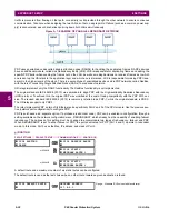
The fixed GOOSE settings are shown below:
PATH: SETTINGS
PRODUCT SETUP
COMMUNICATIONS
IEC 61850 PROTOCOL
GSSE/GOOSE CONFIGURATION
TRANSMISSION
FIXED GOOSE
These settings are applicable to fixed (DNA/UserSt) GOOSE only.
The
GOOSE ID
setting represents the IEC 61850 GOOSE application ID (GoID) name string sent as part of each GOOSE
message. This string identifies the GOOSE message to the receiving device. In revisions previous to 5.0x, this name string
was represented by the
RELAY NAME
setting.
The
DESTINATION MAC
setting allows the destination Ethernet MAC address to be set. This address must be a multicast
address; the least significant bit of the first byte must be set. In F60 releases previous to 5.0x, the destination Ethernet MAC
address was determined automatically by taking the sending MAC address (that is, the unique, local MAC address of the
F60) and setting the multicast bit.
The
GOOSE VLAN PRIORITY
setting indicates the Ethernet priority of GOOSE messages. This allows GOOSE messages to
have higher priority than other Ethernet data. The
GOOSE ETYPE APPID
setting allows the selection of a specific application
ID for each GOOSE sending device. This value can be left at its default if the feature is not required. Both the
GOOSE VLAN
PRIORITY
and
GOOSE ETYPE APPID
settings are required by IEC 61850.
FIXED GOOSE
GOOSE FUNCTION:
Disabled
Range: Enabled, Disabled
MESSAGE
GOOSE ID:
GOOSEOut
Range: 65-character ASCII string
MESSAGE
DESTINATION MAC:
000000000000
Range: standard MAC address
MESSAGE
GOOSE VLAN PRIORITY:
4
Range: 0 to 7 in steps of 1
MESSAGE
GOOSE VLAN ID:
0
Range: 0 to 4095 in steps of 1
MESSAGE
GOOSE ETYPE APPID:
0
Range: 0 to 16383 in steps of 1
Summary of Contents for F60
Page 10: ...x F60 Feeder Protection System GE Multilin TABLE OF CONTENTS ...
Page 30: ...1 20 F60 Feeder Protection System GE Multilin 1 5 USING THE RELAY 1 GETTING STARTED 1 ...
Page 138: ...4 28 F60 Feeder Protection System GE Multilin 4 2 FACEPLATE INTERFACE 4 HUMAN INTERFACES 4 ...
Page 454: ...5 316 F60 Feeder Protection System GE Multilin 5 10 TESTING 5 SETTINGS 5 ...
Page 500: ...7 14 F60 Feeder Protection System GE Multilin 7 1 COMMANDS 7 COMMANDS AND TARGETS 7 ...
Page 508: ...8 8 F60 Feeder Protection System GE Multilin 8 2 FAULT LOCATOR 8 THEORY OF OPERATION 8 ...
Page 522: ...10 12 F60 Feeder Protection System GE Multilin 10 6 DISPOSAL 10 MAINTENANCE 10 ...
Page 660: ...B 116 F60 Feeder Protection System GE Multilin B 4 MEMORY MAPPING APPENDIX B B ...
Page 706: ...E 10 F60 Feeder Protection System GE Multilin E 1 IEC 60870 5 104 APPENDIX E E ...
Page 718: ...F 12 F60 Feeder Protection System GE Multilin F 2 DNP POINT LISTS APPENDIX F F ...
Page 728: ...H 8 F60 Feeder Protection System GE Multilin H 2 ABBREVIATIONS APPENDIX H H Z Impedance Zone ...
Page 730: ...H 10 F60 Feeder Protection System GE Multilin H 3 WARRANTY APPENDIX H H ...


