


GE Multilin
F60 Feeder Protection System
3-29
3 HARDWARE
3.2 WIRING
3
3.2.9 CPU COMMUNICATION PORTS
a) OVERVIEW
In addition to the faceplate RS232 port, the F60 provides a rear RS485 communication port.
The CPU modules do not require a surge ground connection.
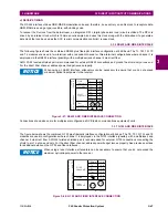
Figure 3–28: CPU MODULE COMMUNICATIONS WIRING
b) RS485 PORTS
RS485 data transmission and reception are accomplished over a single twisted pair with transmit and receive data alternat-
ing over the same two wires. Through the use of the port, continuous monitoring and control from a remote computer,
SCADA system, or PLC is possible.
To minimize errors from noise, the use of shielded twisted pair wire is recommended. Correct polarity must also be
observed. For instance, the relays must be connected with all RS485 “+” terminals connected together, and all RS485 “–”
terminals connected together. Though data is transmitted over a two-wire twisted pair, all RS485 devices require a shared
reference, or common voltage. This common voltage is implied to be a power supply common. Some systems allow the
shield (drain wire) to be used as common wire and to connect directly to the F60 COM terminal (#3); others function cor-
rectly only if the common wire is connected to the F60 COM terminal, but insulated from the shield.
NOTE
842722A3.CDR
100Base-T
COMMON
+
+
—
—
D1a
D2a
D3a
D4b
D4a
BNC
IRIG-B
input
CPU
V
Co-axial cable
Shielded
twisted-pairs
Ground at
remote
device
RS485
COM2
100Base-T
100Base-T
COMMON
+
+
—
—
D1a
D2a
D3a
D4b
D4a
BNC
IRIG-B
input
CPU
U
Co-axial cable
Shielded
twisted-pairs
Ground at
remote
device
RS485
COM2
100Base-T
100Base-FX
Port 1
Port 2
100Base-FX
Tx1
Rx1
COMMON
+
+
—
—
D1a
D2a
D3a
D4b
D4a
BNC
IRIG-B
input
CPU
T
Co-axial cable
Shielded
twisted-pairs
MM fiber-
optic cable
Ground at
remote
device
RS485
COM2
100Base-FX
100Base-FX
Tx2
Rx2
Tx3
Rx3
Tx1
Rx1
Port 3
Port 1
Port 2
Port 3
Port 1
Port 2
Port 3
100Base-FX
Tx1
Rx1
Summary of Contents for F60
Page 10: ...x F60 Feeder Protection System GE Multilin TABLE OF CONTENTS ...
Page 30: ...1 20 F60 Feeder Protection System GE Multilin 1 5 USING THE RELAY 1 GETTING STARTED 1 ...
Page 138: ...4 28 F60 Feeder Protection System GE Multilin 4 2 FACEPLATE INTERFACE 4 HUMAN INTERFACES 4 ...
Page 454: ...5 316 F60 Feeder Protection System GE Multilin 5 10 TESTING 5 SETTINGS 5 ...
Page 500: ...7 14 F60 Feeder Protection System GE Multilin 7 1 COMMANDS 7 COMMANDS AND TARGETS 7 ...
Page 508: ...8 8 F60 Feeder Protection System GE Multilin 8 2 FAULT LOCATOR 8 THEORY OF OPERATION 8 ...
Page 522: ...10 12 F60 Feeder Protection System GE Multilin 10 6 DISPOSAL 10 MAINTENANCE 10 ...
Page 660: ...B 116 F60 Feeder Protection System GE Multilin B 4 MEMORY MAPPING APPENDIX B B ...
Page 706: ...E 10 F60 Feeder Protection System GE Multilin E 1 IEC 60870 5 104 APPENDIX E E ...
Page 718: ...F 12 F60 Feeder Protection System GE Multilin F 2 DNP POINT LISTS APPENDIX F F ...
Page 728: ...H 8 F60 Feeder Protection System GE Multilin H 2 ABBREVIATIONS APPENDIX H H Z Impedance Zone ...
Page 730: ...H 10 F60 Feeder Protection System GE Multilin H 3 WARRANTY APPENDIX H H ...


