


GE Multilin
F60 Feeder Protection System
5-261
5 SETTINGS
5.7 CONTROL ELEMENTS
5
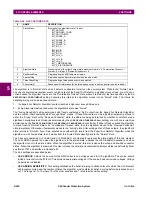
A higher setting would be suitable for a very quiet, well-behaved power system. An initial setting of 5 is suggested if the
user has no previous experience with the Hi-Z element.
•
HI-Z ARCING DET SOE RESET TIME
: An
ARCING DETECTED
event is created upon the detection of arcing by the
expert arc detector algorithm. This setting defines the amount of time to hold creation of any new arcing detected
events. Any subsequent arcing detection during this time will re-start the hold timer. An
ARCING DETECTED DPO
event
is generated upon the expiration of this reset time. The state of the expert arc detector algorithm is unaffected by this
timer. The
HI-Z ARC DETECTED DPO
operand is set to “On” when the
ARCING DETECTED DPO
event is created, and
remains on until an
ARCING DETECTED
event is created.
•
HI-Z PHASE EVENT COUNT
: Specifies how many individual belief-in-arcing indications for a phase current must be
counted in a specified time period before it is determined that an arcing-suspected event exists. These belief-in-arcing
indications are detected by arc detection algorithms (energy and randomness) for a specific set of non-fundamental
frequency component energies. This setting affects only the Hi-Z Arcing Suspected outputs.
•
HI-Z GROUND EVENT COUNT
: Specifies how many individual belief-in-arcing indications for a ground/neutral current
must be counted in a specified time period before it is determined that an arcing-suspected event exists. These belief-
in-arcing indications are detected by arc detection algorithms (energy and randomness) for a specific set of non-funda-
mental frequency component energies. This setting affects only the Hi-Z Arcing Suspected outputs.
•
HI-Z EVENT COUNT TIME
: Specifies the time (in minutes) over which the relay monitors long-term, sporadic, arcing
events for determination of an arcing-suspected event. This setting affects only the Hi-Z Arcing Suspected outputs.
•
HI-Z OC PROTECTION COORD TIMEOUT
: This setting coordinates between the Hi-Z element and conventional
feeder overcurrent protection. A downed conductor or an arcing, intact conductor will not be indicated before the expi-
ration of this timeout, which begins when the Hi-Z element detects a trigger condition (i.e. loss of load, high rate of
change, overcurrent, breaker open, or high belief-in-arcing confidence). Note that this is a minimum operating time; the
actual operating time will depend on the fault characteristics and will likely be significantly longer than this setting.
This value should be such that the conventional feeder overcurrent protection is given an opportunity to operate before
the timeout expires. It is recommended that this timeout value not exceed 30 seconds, because arcing fault current
often diminishes as the fault progresses, making the fault more difficult to detect with increasing time. After the timeout
has expired, at least one additional arc burst must occur in order for the Hi-Z element to proceed with its analysis.
•
HI-Z PHASE OC MIN PICKUP
: Phase overcurrent minimum pickup indicates the level at which the Hi-Z element con-
siders a phase current to be an overcurrent condition. The Hi-Z detection algorithms will ignore all data as long as an
overcurrent condition exists on the system, because it is assumed that conventional feeder overcurrent protection will
clear an overcurrent fault. It is recommended that this setting is above the maximum load current.
•
HI-Z NEUTRAL OC MIN PICKUP
: Neutral overcurrent minimum pickup indicates the level at which the Hi-Z element
considers a neutral current to be an overcurrent condition. The Hi-Z detection algorithms will ignore all data as long as
an overcurrent condition exists on the system, because it is assumed that conventional feeder overcurrent protection
will clear an overcurrent fault. It is recommended that this setting is above the maximum 3Io (residual) current due to
unbalanced loading.
•
HI-Z PHASE RATE OF CHANGE
: Establishes a threshold for determining when a high rate-of-change event occurs on
a phase RMS current. An extremely high rate of change is not characteristic of most high impedance faults; it is more
indicative of a low impedance fault or of the inrush of breaker closing. The inrush current produces substantial varia-
tions in the harmonics used by the high impedance algorithms. Therefore these algorithms ignore all data for several
seconds following a high rate-of-change event that exceeds this setting.
The RMS currents in the Hi-Z algorithms are calculated over a two-cycle time window. The rate-of-change is calculated
as the difference between two consecutive two-cycle RMS readings. The recommended setting is 150 A per two-cycle
interval.
The setting is given in primary amperes
.
•
HI-Z NEUTRAL RATE OF CHANGE
: Establishes a threshold for determining when a high rate-of-change event occurs
on a neutral RMS current. An extremely high rate of change is not characteristic of most high impedance faults; it is
more indicative of a breaker closing, causing associated inrush. The inrush current produces substantial variations in
the harmonics used by the high impedance algorithms. Therefore, these algorithms ignore all data for several seconds
following a high rate-of-change event exceeding this setting.
The RMS currents in the Hi-Z algorithms are calculated over a two-cycle time window. The rate-of-change is calculated
as the difference between two consecutive two-cycle RMS readings. The recommended setting is 150 A per two-cycle
interval.
The setting is given in primary amperes
.
Summary of Contents for F60
Page 10: ...x F60 Feeder Protection System GE Multilin TABLE OF CONTENTS ...
Page 30: ...1 20 F60 Feeder Protection System GE Multilin 1 5 USING THE RELAY 1 GETTING STARTED 1 ...
Page 138: ...4 28 F60 Feeder Protection System GE Multilin 4 2 FACEPLATE INTERFACE 4 HUMAN INTERFACES 4 ...
Page 454: ...5 316 F60 Feeder Protection System GE Multilin 5 10 TESTING 5 SETTINGS 5 ...
Page 500: ...7 14 F60 Feeder Protection System GE Multilin 7 1 COMMANDS 7 COMMANDS AND TARGETS 7 ...
Page 508: ...8 8 F60 Feeder Protection System GE Multilin 8 2 FAULT LOCATOR 8 THEORY OF OPERATION 8 ...
Page 522: ...10 12 F60 Feeder Protection System GE Multilin 10 6 DISPOSAL 10 MAINTENANCE 10 ...
Page 660: ...B 116 F60 Feeder Protection System GE Multilin B 4 MEMORY MAPPING APPENDIX B B ...
Page 706: ...E 10 F60 Feeder Protection System GE Multilin E 1 IEC 60870 5 104 APPENDIX E E ...
Page 718: ...F 12 F60 Feeder Protection System GE Multilin F 2 DNP POINT LISTS APPENDIX F F ...
Page 728: ...H 8 F60 Feeder Protection System GE Multilin H 2 ABBREVIATIONS APPENDIX H H Z Impedance Zone ...
Page 730: ...H 10 F60 Feeder Protection System GE Multilin H 3 WARRANTY APPENDIX H H ...


