


5-276
F60 Feeder Protection System
GE Multilin
5.7 CONTROL ELEMENTS
5 SETTINGS
5
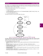
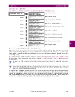
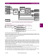
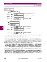
Figure 5–129: ILLUSTRATION OF THE INCIPIENT FAULT DETECTOR ALGORITHM
The following settings are available for each incipient cable fault detector.
•
INCIPIENT FAULT 1 FUNCTION
: This setting enable and disables operation of the incipient fault detection element.
•
INCIPNT FLT 1 BLOCK
: This setting is used to block operation of the incipient cable fault detector element. Assertion
of the FlexLogic™ operand assigned to this setting block operation.
•
INCIPIENT FAULT 1 SOURCE
: This setting selects a current source for the incipient cable fault detector element. This
source must be assigned a valid CT bank.
•
INCIPIENT FAULT 1 PICKUP
: This setting specifies pickup level of the overcurrent detector in per-unit values of the
CT nominal current.
•
INCIPNT FLT 1 MODE
: There are two modes of operation available for the incipient cable fault detector element. In
the “Number of counts” mode, a trip will be initiated only after the selected number of faults is detected. In the “Counts
per window” mode, a trip will be initiated only after the selected number of faults is detected within the time specified by
the
INCIPNT FLT 1 DETECT WINDOW
setting.
•
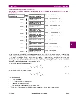
INCIPIENT FLT 1 TRIP COUNTS NUMBER
: This setting selects the number of faults required to initiate a trip.
•
INCIPNT FLT 1 DETECT WINDOW
: This setting specifies a time window for “Counts per window” mode of operation.
•
INCIPIENT FAULT 1 RESET DELAY
: This setting specifies a reset time for the output after the trip is initiated.
0.62
0.64
0.66
0.68
0.70
0.72
0.74
0
1.0
2.0
0.62
0.64
0.66
0.68
0.7
0.72
0.74
–2.0
–1.0
0
1.0
2.0
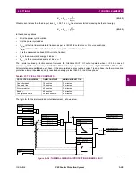
I
N
(neutral current)
I
FB
–0.5
Phase B
Phase C
Phase A
Incipient phase B fault
Curr
ent
(amps)
Curr
ent
(amps)
832774A1.CDR
PHASE CURRENTS
CALCULATED NEUTRAL AND
SUPERIMPOSED PHASE B CURRENT
Summary of Contents for F60
Page 10: ...x F60 Feeder Protection System GE Multilin TABLE OF CONTENTS ...
Page 30: ...1 20 F60 Feeder Protection System GE Multilin 1 5 USING THE RELAY 1 GETTING STARTED 1 ...
Page 138: ...4 28 F60 Feeder Protection System GE Multilin 4 2 FACEPLATE INTERFACE 4 HUMAN INTERFACES 4 ...
Page 454: ...5 316 F60 Feeder Protection System GE Multilin 5 10 TESTING 5 SETTINGS 5 ...
Page 500: ...7 14 F60 Feeder Protection System GE Multilin 7 1 COMMANDS 7 COMMANDS AND TARGETS 7 ...
Page 508: ...8 8 F60 Feeder Protection System GE Multilin 8 2 FAULT LOCATOR 8 THEORY OF OPERATION 8 ...
Page 522: ...10 12 F60 Feeder Protection System GE Multilin 10 6 DISPOSAL 10 MAINTENANCE 10 ...
Page 660: ...B 116 F60 Feeder Protection System GE Multilin B 4 MEMORY MAPPING APPENDIX B B ...
Page 706: ...E 10 F60 Feeder Protection System GE Multilin E 1 IEC 60870 5 104 APPENDIX E E ...
Page 718: ...F 12 F60 Feeder Protection System GE Multilin F 2 DNP POINT LISTS APPENDIX F F ...
Page 728: ...H 8 F60 Feeder Protection System GE Multilin H 2 ABBREVIATIONS APPENDIX H H Z Impedance Zone ...
Page 730: ...H 10 F60 Feeder Protection System GE Multilin H 3 WARRANTY APPENDIX H H ...


