


5-114
F60 Feeder Protection System
GE Multilin
5.4 SYSTEM SETUP
5 SETTINGS
5
The switch element has direct hard-coded connections to IEC 61850 model as shown in the logic diagram. This allows
remote open/close operation of each switch, using either CSWI or XSWI IEC 61850 logical nodes. IEC 61850 select-
before-operate functionality, local/remote switch functionality along with a blocking open/close commands are provided.
Note that IEC 61850 commands are event-driven and dwell time for these is one protection pass only. If you want to main-
tain close/open command for a certain time, do so either on the contact outputs using the "Seal-in" setting or in FlexLogic.
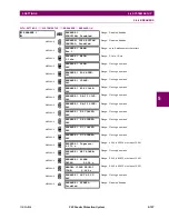
5.4.6 FLEXCURVES
a) SETTINGS
PATH: SETTINGS
SYSTEM SETUP
FLEXCURVES
FLEXCURVE A(D)
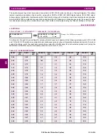
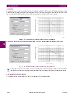
FlexCurves A through D have settings for entering times to reset and operate at the following pickup levels: 0.00 to 0.98
and 1.03 to 20.00. This data is converted into two continuous curves by linear interpolation between data points. To enter a
custom FlexCurve, enter the reset and operate times (using the VALUE keys) for each selected pickup point (using the
MESSAGE UP/DOWN keys) for the desired protection curve (A, B, C, or D).
FLEXCURVE A
FLEXCURVE A TIME AT
0.00 xPKP:
0 ms
Range: 0 to 65535 ms in steps of 1
Table 5–13: FLEXCURVE TABLE
RESET
TIME
MS
RESET
TIME
MS
OPERATE
TIME
MS
OPERATE
TIME
MS
OPERATE
TIME
MS
OPERATE
TIME
MS
0.00
0.68
1.03
2.9
4.9
10.5
0.05
0.70
1.05
3.0
5.0
11.0
0.10
0.72
1.1
3.1
5.1
11.5
0.15
0.74
1.2
3.2
5.2
12.0
0.20
0.76
1.3
3.3
5.3
12.5
0.25
0.78
1.4
3.4
5.4
13.0
0.30
0.80
1.5
3.5
5.5
13.5
0.35
0.82
1.6
3.6
5.6
14.0
0.40
0.84
1.7
3.7
5.7
14.5
0.45
0.86
1.8
3.8
5.8
15.0
0.48
0.88
1.9
3.9
5.9
15.5
0.50
0.90
2.0
4.0
6.0
16.0
0.52
0.91
2.1
4.1
6.5
16.5
0.54
0.92
2.2
4.2
7.0
17.0
0.56
0.93
2.3
4.3
7.5
17.5
0.58
0.94
2.4
4.4
8.0
18.0
0.60
0.95
2.5
4.5
8.5
18.5
0.62
0.96
2.6
4.6
9.0
19.0
0.64
0.97
2.7
4.7
9.5
19.5
0.66
0.98
2.8
4.8
10.0
20.0
Summary of Contents for F60
Page 10: ...x F60 Feeder Protection System GE Multilin TABLE OF CONTENTS ...
Page 30: ...1 20 F60 Feeder Protection System GE Multilin 1 5 USING THE RELAY 1 GETTING STARTED 1 ...
Page 138: ...4 28 F60 Feeder Protection System GE Multilin 4 2 FACEPLATE INTERFACE 4 HUMAN INTERFACES 4 ...
Page 454: ...5 316 F60 Feeder Protection System GE Multilin 5 10 TESTING 5 SETTINGS 5 ...
Page 500: ...7 14 F60 Feeder Protection System GE Multilin 7 1 COMMANDS 7 COMMANDS AND TARGETS 7 ...
Page 508: ...8 8 F60 Feeder Protection System GE Multilin 8 2 FAULT LOCATOR 8 THEORY OF OPERATION 8 ...
Page 522: ...10 12 F60 Feeder Protection System GE Multilin 10 6 DISPOSAL 10 MAINTENANCE 10 ...
Page 660: ...B 116 F60 Feeder Protection System GE Multilin B 4 MEMORY MAPPING APPENDIX B B ...
Page 706: ...E 10 F60 Feeder Protection System GE Multilin E 1 IEC 60870 5 104 APPENDIX E E ...
Page 718: ...F 12 F60 Feeder Protection System GE Multilin F 2 DNP POINT LISTS APPENDIX F F ...
Page 728: ...H 8 F60 Feeder Protection System GE Multilin H 2 ABBREVIATIONS APPENDIX H H Z Impedance Zone ...
Page 730: ...H 10 F60 Feeder Protection System GE Multilin H 3 WARRANTY APPENDIX H H ...


