


GE Multilin
F60 Feeder Protection System
5-229
5 SETTINGS
5.7 CONTROL ELEMENTS
5
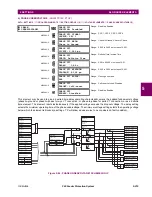
Figure 5–105: TRIP BUS FIELDS IN THE PROTECTION SUMMARY
The following settings are available.
•
TRIP BUS 1 BLOCK
: The trip bus output is blocked when the operand assigned to this setting is asserted.
•
TRIP BUS 1 PICKUP DELAY
: This setting specifies a time delay to produce an output depending on how output is
used.
•
TRIP BUS 1 RESET DELAY
: This setting specifies a time delay to reset an output command. The time delay should be
set long enough to allow the breaker or contactor to perform a required action.
•
TRIP BUS 1 INPUT 1
to
TRIP BUS 1 INPUT 16
: These settings select a FlexLogic operand to be assigned as an input
to the trip bus.
•
TRIP BUS 1 LATCHING
: This setting enables or disables latching of the trip bus output. This is typically used when
lockout is required or user acknowledgement of the relay response is required.
•
TRIP BUS 1 RESET
: The trip bus output is reset when the operand assigned to this setting is asserted. Note that the
RESET OP
operand is pre-wired to the reset gate of the latch, As such, a reset command the front panel interface or via
communications will reset the trip bus output.
Summary of Contents for F60
Page 10: ...x F60 Feeder Protection System GE Multilin TABLE OF CONTENTS ...
Page 30: ...1 20 F60 Feeder Protection System GE Multilin 1 5 USING THE RELAY 1 GETTING STARTED 1 ...
Page 138: ...4 28 F60 Feeder Protection System GE Multilin 4 2 FACEPLATE INTERFACE 4 HUMAN INTERFACES 4 ...
Page 454: ...5 316 F60 Feeder Protection System GE Multilin 5 10 TESTING 5 SETTINGS 5 ...
Page 500: ...7 14 F60 Feeder Protection System GE Multilin 7 1 COMMANDS 7 COMMANDS AND TARGETS 7 ...
Page 508: ...8 8 F60 Feeder Protection System GE Multilin 8 2 FAULT LOCATOR 8 THEORY OF OPERATION 8 ...
Page 522: ...10 12 F60 Feeder Protection System GE Multilin 10 6 DISPOSAL 10 MAINTENANCE 10 ...
Page 660: ...B 116 F60 Feeder Protection System GE Multilin B 4 MEMORY MAPPING APPENDIX B B ...
Page 706: ...E 10 F60 Feeder Protection System GE Multilin E 1 IEC 60870 5 104 APPENDIX E E ...
Page 718: ...F 12 F60 Feeder Protection System GE Multilin F 2 DNP POINT LISTS APPENDIX F F ...
Page 728: ...H 8 F60 Feeder Protection System GE Multilin H 2 ABBREVIATIONS APPENDIX H H Z Impedance Zone ...
Page 730: ...H 10 F60 Feeder Protection System GE Multilin H 3 WARRANTY APPENDIX H H ...


