


5-134
F60 Feeder Protection System
GE Multilin
5.4 SYSTEM SETUP
5 SETTINGS
5
The trigger responds to the frequency signal of the phasor measurement unit (PMU) source. The frequency is calculated
from among phase voltages, auxiliary voltage, phase currents and ground current, in this hierarchy, depending on the
source configuration as per F60 standards. This element requires that the frequency be above the minimum measurable
value. If the frequency is below this value, such as when the circuit is de-energized, the trigger drops out.
•
PMU 1 FREQ TRIGGER LOW-FREQ
: This setting specifies the low threshold for the abnormal frequency trigger. The
comparator applies a 0.02 Hz hysteresis.
•
PMU 1 FREQ TRIGGER HIGH-FREQ
: This setting specifies the high threshold for the abnormal frequency trigger. The
comparator applies a 0.02 Hz hysteresis.
•
PMU 1 FREQ TRIGGER PKP TIME
: This setting can be used to filter out spurious conditions and avoid unnecessary
triggering of the recorder.
•
PMU 1 FREQ TRIGGER DPO TIME
: This setting can be used to extend the trigger after the situation returned to nor-
mal. This setting is of particular importance when using the recorder in the forced mode (recording as long as the trig-
gering condition is asserted).
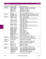
Figure 5–48: FREQUENCY TRIGGER SCHEME LOGIC
g) VOLTAGE TRIGGERING
PATH: SETTINGS
SYSTEM SETUP
PHASOR MEASUREMENT...
PMU 1 TRIGGERING
PMU 1 VOLTAGE TRIGGER
PMU 1 VOLTAGE
TRIGGER
PMU 1 VOLT TRIGGER
FUNCTION: Disabled
Range: Enabled, Disabled
MESSAGE
PMU 1 VOLT TRIGGER
LOW-VOLT: 0.800 pu
Range: 0.250 to 1.250 pu in steps of 0.001
MESSAGE
PMU 1 VOLT TRIGGER
HIGH-VOLT: 1.200 pu
Range: 0.750 to 1.750 pu in steps of 0.001
MESSAGE
PMU 1 VOLT TRIGGER
PKP TIME: 0.10 s
Range: 0.00 to 600.00 s in steps of 0.01
MESSAGE
PMU 1 VOLT TRIGGER
DPO TIME: 1.00 s
Range: 0.00 to 600.00 s in steps of 0.01
MESSAGE
PMU 1 VOLT TRIG BLK:
Off
Range: FlexLogic operand
MESSAGE
PMU 1 VOLT TRIGGER
TARGET: Self-Reset
Range: Self-Reset, Latched, Disabled
MESSAGE
PMU 1 VOLT TRIGGER
EVENTS: Disabled
Range: Enabled, Disabled
SETTINGS
PMU 1 FREQ TRIGGER
FUNCTION:
Enabled = 1
PMU 1 FREQ TRIG BLK:
Off = 0
SETTING
PMU 1 SIGNAL
SOURCE:
FREQUENCY, f
AND
SETTINGS
PMU 1 FREQ TRIGGER LOW-FREQ:
PMU 1 FREQ TRIGGER HIGH-FREQ:
0< f < LOW-FREQ
OR
f > HIGH-FREQ
RUN
SETTINGS
PMU 1 FREQ TRIGGER PKP TIME:
PMU 1 FREQ TRIGGER DPO TIME:
t
DPO
FLEXLOGIC OPERAND
PMU 1 FREQ TRIGGER
FLEXLOGIC OPERANDS
PMU 1 VOLT TRIGGER
PMU 1 CURR TRIGGER
PMU 1 POWER TRIGGER
PMU 1 ROCOF TRIGGER
SETTING
PMU 1 USER TRIGGER:
Off = 0
OR
FLEXLOGIC OPERAND
PMU 1 TRIGGERED
to STAT bits of
the data frame
847008A1.CDR
SETTINGS
PKP
t
0
0
Summary of Contents for F60
Page 10: ...x F60 Feeder Protection System GE Multilin TABLE OF CONTENTS ...
Page 30: ...1 20 F60 Feeder Protection System GE Multilin 1 5 USING THE RELAY 1 GETTING STARTED 1 ...
Page 138: ...4 28 F60 Feeder Protection System GE Multilin 4 2 FACEPLATE INTERFACE 4 HUMAN INTERFACES 4 ...
Page 454: ...5 316 F60 Feeder Protection System GE Multilin 5 10 TESTING 5 SETTINGS 5 ...
Page 500: ...7 14 F60 Feeder Protection System GE Multilin 7 1 COMMANDS 7 COMMANDS AND TARGETS 7 ...
Page 508: ...8 8 F60 Feeder Protection System GE Multilin 8 2 FAULT LOCATOR 8 THEORY OF OPERATION 8 ...
Page 522: ...10 12 F60 Feeder Protection System GE Multilin 10 6 DISPOSAL 10 MAINTENANCE 10 ...
Page 660: ...B 116 F60 Feeder Protection System GE Multilin B 4 MEMORY MAPPING APPENDIX B B ...
Page 706: ...E 10 F60 Feeder Protection System GE Multilin E 1 IEC 60870 5 104 APPENDIX E E ...
Page 718: ...F 12 F60 Feeder Protection System GE Multilin F 2 DNP POINT LISTS APPENDIX F F ...
Page 728: ...H 8 F60 Feeder Protection System GE Multilin H 2 ABBREVIATIONS APPENDIX H H Z Impedance Zone ...
Page 730: ...H 10 F60 Feeder Protection System GE Multilin H 3 WARRANTY APPENDIX H H ...


