


GE Multilin
F60 Feeder Protection System
5-93
5 SETTINGS
5.2 PRODUCT SETUP
5
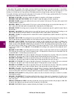
EXAMPLE 1: EXTENDING THE INPUT/OUTPUT CAPABILITIES OF A UR-SERIES RELAY
Consider an application that requires additional quantities of contact inputs or output contacts or lines of programmable
logic that exceed the capabilities of a single UR-series chassis. The problem is solved by adding an extra UR-series IED,
such as the C30, to satisfy the additional input and output and programmable logic requirements. The two IEDs are con-
nected via single-channel digital communication cards as shown in the figure below.
Figure 5–18: INPUT AND OUTPUT EXTENSION VIA DIRECT INPUTS AND OUTPUTS
In the above application, the following settings should be applied. For UR-series IED 1:
DIRECT OUTPUT DEVICE ID:
“1”
DIRECT I/O CH1 RING CONFIGURATION:
“Yes”
DIRECT I/O DATA RATE:
“128 kbps”
For UR-series IED 2:
DIRECT OUTPUT DEVICE ID:
“2”
DIRECT I/O CH1 RING CONFIGURATION:
“Yes”
DIRECT I/O DATA RATE:
“128 kbps”
The message delivery time is about 0.2 of power cycle in both ways (at 128 kbps); that is, from device 1 to device 2, and
from device 2 to device 1. Different communications cards can be selected by the user for this back-to-back connection (for
example: fiber, G.703, or RS422).
EXAMPLE 2: INTERLOCKING BUSBAR PROTECTION
A simple interlocking busbar protection scheme could be accomplished by sending a blocking signal from downstream
devices, say 2, 3, and 4, to the upstream device that monitors a single incomer of the busbar, as shown below.
Figure 5–19: SAMPLE INTERLOCKING BUSBAR PROTECTION SCHEME
For increased reliability, a dual-ring configuration (shown below) is recommended for this application.
842711A1.CDR
UR IED 1
TX1
RX1
UR IED 2
TX1
RX1
842712A1.CDR
UR IED 1
UR IED 2
UR IED 4
UR IED 3
BLOCK
Summary of Contents for F60
Page 10: ...x F60 Feeder Protection System GE Multilin TABLE OF CONTENTS ...
Page 30: ...1 20 F60 Feeder Protection System GE Multilin 1 5 USING THE RELAY 1 GETTING STARTED 1 ...
Page 138: ...4 28 F60 Feeder Protection System GE Multilin 4 2 FACEPLATE INTERFACE 4 HUMAN INTERFACES 4 ...
Page 454: ...5 316 F60 Feeder Protection System GE Multilin 5 10 TESTING 5 SETTINGS 5 ...
Page 500: ...7 14 F60 Feeder Protection System GE Multilin 7 1 COMMANDS 7 COMMANDS AND TARGETS 7 ...
Page 508: ...8 8 F60 Feeder Protection System GE Multilin 8 2 FAULT LOCATOR 8 THEORY OF OPERATION 8 ...
Page 522: ...10 12 F60 Feeder Protection System GE Multilin 10 6 DISPOSAL 10 MAINTENANCE 10 ...
Page 660: ...B 116 F60 Feeder Protection System GE Multilin B 4 MEMORY MAPPING APPENDIX B B ...
Page 706: ...E 10 F60 Feeder Protection System GE Multilin E 1 IEC 60870 5 104 APPENDIX E E ...
Page 718: ...F 12 F60 Feeder Protection System GE Multilin F 2 DNP POINT LISTS APPENDIX F F ...
Page 728: ...H 8 F60 Feeder Protection System GE Multilin H 2 ABBREVIATIONS APPENDIX H H Z Impedance Zone ...
Page 730: ...H 10 F60 Feeder Protection System GE Multilin H 3 WARRANTY APPENDIX H H ...


