


GE Multilin
F60 Feeder Protection System
5-165
5 SETTINGS
5.5 FLEXLOGIC
5
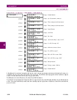
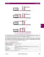
Figure 5–64: FLEXELEMENT INPUT MODE SETTING
The
FLEXELEMENT 1 PICKUP
setting specifies the operating threshold for the effective operating signal of the element. If set
to “Over”, the element picks up when the operating signal exceeds the
FLEXELEMENT 1 PICKUP
value. If set to “Under”, the
element picks up when the operating signal falls below the
FLEXELEMENT 1 PICKUP
value.
The
FLEXELEMENT 1 HYSTERESIS
setting controls the element dropout. It should be noticed that both the operating signal
and the pickup threshold can be negative facilitating applications such as reverse power alarm protection. The FlexElement
can be programmed to work with all analog actual values measured by the relay. The
FLEXELEMENT 1 PICKUP
setting is
entered in per-unit values using the following definitions of the base units:
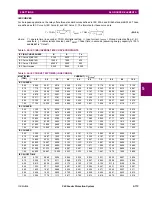
Table 5–21: FLEXELEMENT BASE UNITS
BREAKER ACC ARCING AMPS
(Brk X Acc Arc Amp A, B, and C)
BASE = 2000 kA
2
×
cycle
BREAKER ARCING AMPS
(Brk X Arc Amp A, B, and C)
BASE = 1 kA
2
×
cycle
DCmA
BASE = maximum value of the
DCMA INPUT MAX
setting for the two transducers configured
under the +IN and –IN inputs.
DELTA TIME
BASE = 1 µs
FAULT LOCATION
BASE = Line Length as specified in Fault Report
FREQUENCY
f
BASE
= 1 Hz
FREQUENCY RATE OF CHANGE
df/dt
BASE
= 1 Hz/s
842706A2.CDR
FlexElement 1 OpSig
FLEXELEMENT 1 PKP
FLEXELEMENT
DIRECTION = Over;
FLEXELEMENT INPUT
MODE = Signed;
FlexElement 1 OpSig
FLEXELEMENT 1 PKP
FLEXELEMENT
DIRECTION = Over;
FLEXELEMENT INPUT
MODE = Absolute;
FlexElement 1 OpSig
FLEXELEMENT 1 PKP
FLEXELEMENT
DIRECTION = Under;
FLEXELEMENT INPUT
MODE = Signed;
FlexElement 1 OpSig
FLEXELEMENT 1 PKP
FLEXELEMENT
DIRECTION = Under;
FLEXELEMENT INPUT
MODE = Absolute;
Summary of Contents for F60
Page 10: ...x F60 Feeder Protection System GE Multilin TABLE OF CONTENTS ...
Page 30: ...1 20 F60 Feeder Protection System GE Multilin 1 5 USING THE RELAY 1 GETTING STARTED 1 ...
Page 138: ...4 28 F60 Feeder Protection System GE Multilin 4 2 FACEPLATE INTERFACE 4 HUMAN INTERFACES 4 ...
Page 454: ...5 316 F60 Feeder Protection System GE Multilin 5 10 TESTING 5 SETTINGS 5 ...
Page 500: ...7 14 F60 Feeder Protection System GE Multilin 7 1 COMMANDS 7 COMMANDS AND TARGETS 7 ...
Page 508: ...8 8 F60 Feeder Protection System GE Multilin 8 2 FAULT LOCATOR 8 THEORY OF OPERATION 8 ...
Page 522: ...10 12 F60 Feeder Protection System GE Multilin 10 6 DISPOSAL 10 MAINTENANCE 10 ...
Page 660: ...B 116 F60 Feeder Protection System GE Multilin B 4 MEMORY MAPPING APPENDIX B B ...
Page 706: ...E 10 F60 Feeder Protection System GE Multilin E 1 IEC 60870 5 104 APPENDIX E E ...
Page 718: ...F 12 F60 Feeder Protection System GE Multilin F 2 DNP POINT LISTS APPENDIX F F ...
Page 728: ...H 8 F60 Feeder Protection System GE Multilin H 2 ABBREVIATIONS APPENDIX H H Z Impedance Zone ...
Page 730: ...H 10 F60 Feeder Protection System GE Multilin H 3 WARRANTY APPENDIX H H ...


