


GE Multilin
F60 Feeder Protection System
5-151
5 SETTINGS
5.5 FLEXLOGIC
5
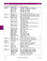
ELEMENT:
Phase time
overcurrent
PHASE TOC1 PKP
PHASE TOC1 OP
PHASE TOC1 DPO
PHASE TOC1 PKP A
PHASE TOC1 PKP B
PHASE TOC1 PKP C
PHASE TOC1 OP A
PHASE TOC1 OP B
PHASE TOC1 OP C
PHASE TOC1 DPO A
PHASE TOC1 DPO B
PHASE TOC1 DPO C
At least one phase of phase time overcurrent 1 has picked up
At least one phase of phase time overcurrent 1 has operated
All phases of phase time overcurrent 1 have dropped out
Phase A of phase time overcurrent 1 has picked up
Phase B of phase time overcurrent 1 has picked up
Phase C of phase time overcurrent 1 has picked up
Phase A of phase time overcurrent 1 has operated
Phase B of phase time overcurrent 1 has operated
Phase C of phase time overcurrent 1 has operated
Phase A of phase time overcurrent 1 has dropped out
Phase B of phase time overcurrent 1 has dropped out
Phase C of phase time overcurrent 1 has dropped out
PHASE TOC2 to 4
Same set of operands as shown for PHASE TOC1
ELEMENT:
Phase undervoltage
PHASE UV1 PKP
PHASE UV1 OP
PHASE UV1 DPO
PHASE UV1 PKP A
PHASE UV1 PKP B
PHASE UV1 PKP C
PHASE UV1 OP A
PHASE UV1 OP B
PHASE UV1 OP C
PHASE UV1 DPO A
PHASE UV1 DPO B
PHASE UV1 DPO C
At least one phase of phase undervoltage 1 has picked up
At least one phase of phase undervoltage 1 has operated
All phases of phase undervoltage 1 have dropped out
Phase A of phase undervoltage 1 has picked up
Phase B of phase undervoltage 1 has picked up
Phase C of phase undervoltage 1 has picked up
Phase A of phase undervoltage 1 has operated
Phase B of phase undervoltage 1 has operated
Phase C of phase undervoltage 1 has operated
Phase A of phase undervoltage 1 has dropped out
Phase B of phase undervoltage 1 has dropped out
Phase C of phase undervoltage 1 has dropped out
PHASE UV2 to 3
Same set of operands as shown for PHASE UV1
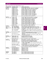
ELEMENT:
Synchrophasor
phasor
measurement unit
(PMU)
PMU Agg 1 SvEng On
PMU 1 CURR TRIGGER
PMU 1 FREQ TRIGGER
PMU 1 POWER TRIGGER
PMU 1 ROCOF TRIGGER
PMU 1 VOLT TRIGGER
PMU 1 TRIGGERED
SvEng data item in associated control block is on
Overcurrent trigger of phasor measurement unit 1 has operated
Abnormal frequency trigger of phasor measurement unit 1 has operated
Overpower trigger of phasor measurement unit 1 has operated
Rate of change of frequency trigger of phasor measurement unit 1 has
operated
Abnormal voltage trigger of phasor measurement unit 1 has operated
Phasor measurement unit 1 triggered; no events or targets are generated by
this operand
ELEMENT:
Synchrophasor one-
shot
PMU ONE-SHOT EXPIRED
PMU ONE-SHOT OP
PMU ONE-SHOT PENDING
Indicates the one-shot operation has been executed, and the present time is
at least 30 seconds past the scheduled one-shot time
Indicates the one-shot operation and remains asserted for 30 seconds
afterwards
Indicates the one-shot operation is pending; that is, the present time is before
the scheduled one-shot time
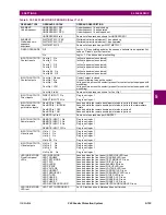
ELEMENT:
Restricted ground
fault
RESTD GND FT1 PKP
RESTD GND FT1 OP
RESTD GND FT1 DPO
Restricted ground fault 1 has picked up
Restricted ground fault 1 has operated
Restricted ground fault 1 has dropped out
RESTD GND FT2 to 6
Same set of operands as shown for RESTD GND FT1
ELEMENT:
Selector switch
SELECTOR 1 POS Y
SELECTOR 1 BIT 0
SELECTOR 1 BIT 1
SELECTOR 1 BIT 2
SELECTOR 1 STP ALARM
SELECTOR 1 BIT ALARM
SELECTOR 1 ALARM
SELECTOR 1 PWR ALARM
Selector switch 1 is in Position Y (mutually exclusive operands)
First bit of the 3-bit word encoding position of selector 1
Second bit of the 3-bit word encoding position of selector 1
Third bit of the 3-bit word encoding position of selector 1
Position of selector 1 has been pre-selected with the stepping up control
input but not acknowledged
Position of selector 1 has been pre-selected with the 3-bit control input but
not acknowledged
Position of selector 1 has been pre-selected but not acknowledged
Position of selector switch 1 is undetermined or restored from memory when
the relay powers up and synchronizes to the three-bit input
SELECTOR 2
Same set of operands as shown above for SELECTOR 1
ELEMENT:
Setting group
SETTING GROUP ACT 1
SETTING GROUP ACT 2
SETTING GROUP ACT 3
SETTING GROUP ACT 4
SETTING GROUP ACT 5
SETTING GROUP ACT 6
Setting group 1 is active
Setting group 2 is active
Setting group 3 is active
Setting group 4 is active
Setting group 5 is active
Setting group 6 is active
ELEMENT:
Disturbance
detector
SRC1 50DD OP
SRC2 50DD OP
SRC3 50DD OP
SRC4 50DD OP
Source 1 disturbance detector has operated
Source 2 disturbance detector has operated
Source 3 disturbance detector has operated
Source 4 disturbance detector has operated
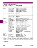
Table 5–18: F60 FLEXLOGIC OPERANDS (Sheet 5 of 8)
OPERAND TYPE
OPERAND SYNTAX
OPERAND DESCRIPTION
Summary of Contents for F60
Page 10: ...x F60 Feeder Protection System GE Multilin TABLE OF CONTENTS ...
Page 30: ...1 20 F60 Feeder Protection System GE Multilin 1 5 USING THE RELAY 1 GETTING STARTED 1 ...
Page 138: ...4 28 F60 Feeder Protection System GE Multilin 4 2 FACEPLATE INTERFACE 4 HUMAN INTERFACES 4 ...
Page 454: ...5 316 F60 Feeder Protection System GE Multilin 5 10 TESTING 5 SETTINGS 5 ...
Page 500: ...7 14 F60 Feeder Protection System GE Multilin 7 1 COMMANDS 7 COMMANDS AND TARGETS 7 ...
Page 508: ...8 8 F60 Feeder Protection System GE Multilin 8 2 FAULT LOCATOR 8 THEORY OF OPERATION 8 ...
Page 522: ...10 12 F60 Feeder Protection System GE Multilin 10 6 DISPOSAL 10 MAINTENANCE 10 ...
Page 660: ...B 116 F60 Feeder Protection System GE Multilin B 4 MEMORY MAPPING APPENDIX B B ...
Page 706: ...E 10 F60 Feeder Protection System GE Multilin E 1 IEC 60870 5 104 APPENDIX E E ...
Page 718: ...F 12 F60 Feeder Protection System GE Multilin F 2 DNP POINT LISTS APPENDIX F F ...
Page 728: ...H 8 F60 Feeder Protection System GE Multilin H 2 ABBREVIATIONS APPENDIX H H Z Impedance Zone ...
Page 730: ...H 10 F60 Feeder Protection System GE Multilin H 3 WARRANTY APPENDIX H H ...


