


GE Multilin
F60 Feeder Protection System
5-299
5 SETTINGS
5.8 INPUTS/OUTPUTS
5
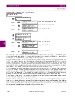
DIRECT INPUT 9 DEVICE ID
: "4"
DIRECT INPUT 9 BIT NUMBER
: "3"
DIRECT INPUT 9 DEFAULT STATE
: select "On" for security, select "Off" for dependability
Now the three blocking signals are available in UR IED 1 as
DIRECT INPUT 7 ON
,
DIRECT INPUT 8 ON
, and
DIRECT INPUT 9
ON
. Upon losing communications or a device, the scheme is inclined to block (if any default state is set to “On”), or to trip
the bus on any overcurrent condition (all default states set to “Off”).
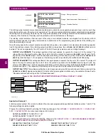
EXAMPLE 2: PILOT-AIDED SCHEMES
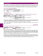
Consider a three-terminal line protection application shown in the figure below.
Figure 5–143: THREE-TERMINAL LINE APPLICATION
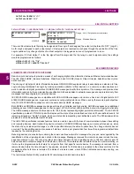
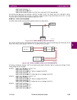
Assume the Hybrid Permissive Overreaching Transfer Trip (Hybrid POTT) scheme is applied using the architecture shown
below. The scheme output operand
HYB POTT TX1
is used to key the permission.
Figure 5–144: SINGLE-CHANNEL OPEN-LOOP CONFIGURATION
In the above architecture, Devices 1 and 3 do not communicate directly. Therefore, Device 2 must act as a ‘bridge’. The fol-
lowing settings should be applied:
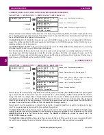
UR IED 1:
DIRECT OUT 2 OPERAND:
"
HYB POTT TX1
"
DIRECT INPUT 5 DEVICE ID:
"2"
DIRECT INPUT 5 BIT NUMBER:
"2" (this is a message from IED 2)
DIRECT INPUT 6 DEVICE ID:
"2"
DIRECT INPUT 6 BIT NUMBER:
"4" (effectively, this is a message from IED 3)
UR IED 3:
DIRECT OUT 2 OPERAND:
"
HYB POTT TX1
"
DIRECT INPUT 5 DEVICE ID:
"2"
DIRECT INPUT 5 BIT NUMBER:
"2" (this is a message from IED 2)
DIRECT INPUT 6 DEVICE ID:
"2"
DIRECT INPUT 6 BIT NUMBER:
"3" (effectively, this is a message from IED 1)
UR IED 2:
DIRECT INPUT 5 DEVICE ID:
"1"
DIRECT INPUT 5 BIT NUMBER:
"2"
DIRECT INPUT 6 DEVICE ID:
"3"
DIRECT INPUT 6 BIT NUMBER:
"2"
842713A1.CDR
UR IED 1
UR IED 2
UR IED 3
842714A1.CDR
UR IED 1
TX1
RX1
UR IED 2
RX2
TX2
RX1
TX1
UR IED 3
RX1
TX1
Summary of Contents for F60
Page 10: ...x F60 Feeder Protection System GE Multilin TABLE OF CONTENTS ...
Page 30: ...1 20 F60 Feeder Protection System GE Multilin 1 5 USING THE RELAY 1 GETTING STARTED 1 ...
Page 138: ...4 28 F60 Feeder Protection System GE Multilin 4 2 FACEPLATE INTERFACE 4 HUMAN INTERFACES 4 ...
Page 454: ...5 316 F60 Feeder Protection System GE Multilin 5 10 TESTING 5 SETTINGS 5 ...
Page 500: ...7 14 F60 Feeder Protection System GE Multilin 7 1 COMMANDS 7 COMMANDS AND TARGETS 7 ...
Page 508: ...8 8 F60 Feeder Protection System GE Multilin 8 2 FAULT LOCATOR 8 THEORY OF OPERATION 8 ...
Page 522: ...10 12 F60 Feeder Protection System GE Multilin 10 6 DISPOSAL 10 MAINTENANCE 10 ...
Page 660: ...B 116 F60 Feeder Protection System GE Multilin B 4 MEMORY MAPPING APPENDIX B B ...
Page 706: ...E 10 F60 Feeder Protection System GE Multilin E 1 IEC 60870 5 104 APPENDIX E E ...
Page 718: ...F 12 F60 Feeder Protection System GE Multilin F 2 DNP POINT LISTS APPENDIX F F ...
Page 728: ...H 8 F60 Feeder Protection System GE Multilin H 2 ABBREVIATIONS APPENDIX H H Z Impedance Zone ...
Page 730: ...H 10 F60 Feeder Protection System GE Multilin H 3 WARRANTY APPENDIX H H ...


