


GE Multilin
F60 Feeder Protection System
B-19
APPENDIX B
B.4 MEMORY MAPPING
B
2198
Breaker Flashover 1 Side 2 Source
0 to 6
---
1
F211
0 (None)
2199
Breaker Flashover 1 Status Closed A
0 to 4294967295
---
1
F300
0
219B
Breaker Flashover 1 Status Closed B
0 to 4294967295
---
1
F300
0
219D
Breaker Flashover 1 Status Closed C
0 to 4294967295
---
1
F300
0
219F
Breaker Flashover 1 Voltage Pickup Level
0 to 1.5
pu
0.001
F001
850
21A0
Breaker Flashover 1 Voltage Difference Pickup Level
0 to 100000
V
1
F060
1000
21A2
Breaker Flashover 1 Current Pickup Level
0 to 1.5
pu
0.001
F001
600
21A3
Breaker Flashover 1 Pickup Delay
0 to 65.535
s
0.001
F001
100
21A4
Breaker Flashover 1 Supervision Phase A
0 to 4294967295
---
1
F300
0
21A6
Breaker Flashover 1 Supervision Phase B
0 to 4294967295
---
1
F300
0
21A8
Breaker Flashover 1 Supervision Phase C
0 to 4294967295
---
1
F300
0
21AA
Breaker Flashover 1 Block
0 to 4294967295
---
1
F300
0
21AC
Breaker Flashover 1 Events
0 to 1
---
1
F102
0 (Disabled)
21AD
Breaker Flashover 1 Target
0 to 2
---
1
F109
0 (Self-Reset)
21AE
Reserved (4 items)
---
---
---
F001
0
21B2
...Repeated for Breaker Flashover 2
Breaker Arcing Current Actual Values (Read Only Non-Volatile) (2 modules)
21E0
Breaker 1 Arcing Current Phase A
0 to 99999999
kA
2
-cyc
1
F060
0
21E2
Breaker 1 Arcing Current Phase B
0 to 99999999
kA
2
-cyc
1
F060
0
Breaker Arcing Current Actual Values (Read Only Non-Volatile) (2 modules)
21E4
Breaker 1 Arcing Current Phase C
0 to 99999999
kA
2
-cyc
1
F060
0
Breaker Arcing Current Actual Values (Read Only Non-Volatile) (2 modules)
21E6
Breaker 1 Operating Time Phase A
0 to 65535
ms
1
F001
0
21E7
Breaker 1 Operating Time Phase B
0 to 65535
ms
1
F001
0
Breaker Arcing Current Actual Values (Read Only Non-Volatile) (2 modules)
21E8
Breaker 1 Operating Time Phase C
0 to 65535
ms
1
F001
0
21E9
Breaker 1 Operating Time
0 to 65535
ms
1
F001
0
21EA
...Repeated for module number 2
Breaker Arcing Current Actual Values (Read Only Non-Volatile) (2 modules)
21EE
...Repeated for module number 2
Breaker Arcing Current Actual Values (Read Only Non-Volatile) (2 modules)
21F0
...Repeated for module number 2
Breaker Arcing Current Actual Values (Read Only Non-Volatile) (2 modules)
21F2
...Repeated for module number 2
Breaker Arcing Current Commands (Read/Write Command) (2 modules)
2224
Breaker 1 Arcing Current Clear Command
0 to 1
---
1
F126
0 (No)
2225
Breaker 2 Arcing Current Clear Command
0 to 1
---
1
F126
0 (No)
Passwords Unauthorized Access (Read/Write Command)
2230
Reset Unauthorized Access
0 to 1
---
1
F126
0 (No)
Hi-Z (High Impedance Fault Detection) Commands (Read/Write Command)
2240
Hi-Z Clear Oscillography
0 to 1
---
1
F126
0 (No)
2241
Hi-Z Oscillography Force Trigger
0 to 1
---
1
F126
0 (No)
2242
Hi-Z Oscillography Force Algorithm Capture
0 to 1
---
1
F126
0 (No)
2243
Hi-Z Reset Sigma Values
0 to 1
---
1
F126
0 (No)
Hi-Z (High Impedance Fault Detection) Status (Read Only)
2250
Hi-Z Status
0 to 9
---
1
F187
0 (NORMAL)
2251
Hi-Z Phase A Arc Confidence
0 to 100
---
1
F001
0
2252
Hi-Z Phase B Arc Confidence
0 to 100
---
1
F001
0
2253
Hi-Z Phase C Arc Confidence
0 to 100
---
1
F001
0
2254
Hi-Z Neutral Arc Confidence
0 to 100
---
1
F001
0
Hi-Z (High Impedance Fault Detection) Records (Read Only) (4 modules)
2260
Hi-Z Capture 1 Trigger Type
0 to 6
---
1
F188
0 (NONE)
2261
Hi-Z Capture 1 Time
0 to 1
---
1
F050
0
2263
...Repeated for Hi-Z Capture 2
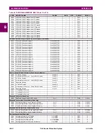
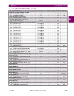
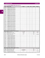
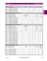
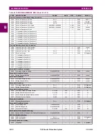
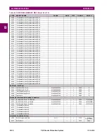
Table B–10: MODBUS MEMORY MAP (Sheet 11 of 70)
ADDR
REGISTER NAME
RANGE
UNITS
STEP
FORMAT
DEFAULT
Summary of Contents for F60
Page 10: ...x F60 Feeder Protection System GE Multilin TABLE OF CONTENTS ...
Page 30: ...1 20 F60 Feeder Protection System GE Multilin 1 5 USING THE RELAY 1 GETTING STARTED 1 ...
Page 138: ...4 28 F60 Feeder Protection System GE Multilin 4 2 FACEPLATE INTERFACE 4 HUMAN INTERFACES 4 ...
Page 454: ...5 316 F60 Feeder Protection System GE Multilin 5 10 TESTING 5 SETTINGS 5 ...
Page 500: ...7 14 F60 Feeder Protection System GE Multilin 7 1 COMMANDS 7 COMMANDS AND TARGETS 7 ...
Page 508: ...8 8 F60 Feeder Protection System GE Multilin 8 2 FAULT LOCATOR 8 THEORY OF OPERATION 8 ...
Page 522: ...10 12 F60 Feeder Protection System GE Multilin 10 6 DISPOSAL 10 MAINTENANCE 10 ...
Page 660: ...B 116 F60 Feeder Protection System GE Multilin B 4 MEMORY MAPPING APPENDIX B B ...
Page 706: ...E 10 F60 Feeder Protection System GE Multilin E 1 IEC 60870 5 104 APPENDIX E E ...
Page 718: ...F 12 F60 Feeder Protection System GE Multilin F 2 DNP POINT LISTS APPENDIX F F ...
Page 728: ...H 8 F60 Feeder Protection System GE Multilin H 2 ABBREVIATIONS APPENDIX H H Z Impedance Zone ...
Page 730: ...H 10 F60 Feeder Protection System GE Multilin H 3 WARRANTY APPENDIX H H ...


