


GE Multilin
F60 Feeder Protection System
2-9
2 PRODUCT DESCRIPTION
2.2 ORDER CODES
2
MOUNT/COATING
H
|
|
|
|
|
|
|
|
Horizontal (19” rack) - Standard
A
|
|
|
|
|
|
|
|
Horizontal (19” rack) - With harsh environmental coating
FACEPLATE/ DISPLAY
C
|
|
|
|
|
|
|
English display
D
|
|
|
|
|
|
|
French display
R
|
|
|
|
|
|
|
Russian display
A
|
|
|
|
|
|
|
Chinese display
P
|
|
|
|
|
|
|
English display with 4 small and 12 large programmable pushbuttons
G
|
|
|
|
|
|
|
French display with 4 small and 12 large programmable pushbuttons
S
|
|
|
|
|
|
|
Russian display with 4 small and 12 large programmable pushbuttons
B
|
|
|
|
|
|
|
Chinese display with 4 small and 12 large programmable pushbuttons
K
|
|
|
|
|
|
|
Enhanced front panel with English display
M
|
|
|
|
|
|
|
Enhanced front panel with French display
Q
|
|
|
|
|
|
|
Enhanced front panel with Russian display
U
|
|
|
|
|
|
|
Enhanced front panel with Chinese display
L
|
|
|
|
|
|
|
Enhanced front panel with English display and user-programmable pushbuttons
N
|
|
|
|
|
|
|
Enhanced front panel with French display and user-programmable pushbuttons
T
|
|
|
|
|
|
|
Enhanced front panel with Russian display and user-programmable pushbuttons
V
|
|
|
|
|
|
|
Enhanced front panel with Chinese display and user-programmable pushbuttons
W
|
|
|
|
|
|
|
Enhanced front panel with Turkish display
Y
|
|
|
|
|
|
|
Enhanced front panel with Turkish display and user-programmable pushbuttons
I
|
|
|
|
|
|
|
Enhanced front panel with German display
J
|
|
|
|
|
|
|
Enhanced front panel with German display and user-programmable pushbuttons
POWER SUPPLY
(redundant supply must
be same type as main supply)
H
|
|
|
|
|
|
125 / 250 V AC/DC power supply
H
|
|
|
|
|
SH
125 / 250 V AC/DC with redundant 125 / 250 V AC/DC power supply
L
|
|
|
|
|
|
24 to 48 V (DC only) power supply
L
|
|
|
|
|
SL
24 to 48 V (DC only) with redundant 24 to 48 V DC power supply
ENHANCED DIAGNOSTICS CT/VT DSP
(8L, 8M, 8N, 8R require DSP to be enhanced diagnostic)
|
|
XX
|
XX
|
No DSP module (slots M and U only)
8L
|
8L
|
|
|
Standard 4CT/4VT with enhanced diagnostics
8M
|
8M
|
|
|
Sensitive Ground 4CT/4VT with enhanced diagnostics
8N
|
8N
|
|
|
Standard 8CT with enhanced diagnostics
8R
|
8R
|
|
|
Sensitive Ground 8CT with enhanced diagnostics
|
|
8Z *
|
|
|
Hi-Z 4CT (required for high-impedance fault detection element)
DIGITAL INPUTS/OUTPUTS
XX
XX
XX
XX
XX
No Module
4A
4A
4A
4A
4A
4 Solid-State (no monitoring) MOSFET outputs
4B
4B
4B
4B
4B
4 Solid-State (voltage with optional current) MOSFET outputs
4C
4C
4C
4C
4C
4 Solid-State (current with optional voltage) MOSFET outputs
4D
4D
4D
4D
4D
16 digital inputs with Auto-Burnishing (maximum of three modules within a case)
4L
4L
4L
4L
4L
14 Form-A (no monitoring) Latching outputs
67
67
67
67
67
8 Form-A (no monitoring) outputs
6A
6A
6A
6A
6A
2 Form-A (voltage with optional current) and 2 Form-C outputs, 8 digital inputs
6B
6B
6B
6B
6B
2 Form-A (voltage with optional current) and 4 Form-C outputs, 4 digital inputs
6C
6C
6C
6C
6C
8 Form-C outputs
6D
6D
6D
6D
6D
16 digital inputs
6E
6E
6E
6E
6E
4 Form-C outputs, 8 digital inputs
6F
6F
6F
6F
6F
8 Fast Form-C outputs
6G
6G
6G
6G
6G
4 Form-A (voltage with optional current) outputs, 8 digital inputs
6H
6H
6H
6H
6H
6 Form-A (voltage with optional current) outputs, 4 digital inputs
6K
6K
6K
6K
6K
4 Form-C and 4 Fast Form-C outputs
6L
6L
6L
6L
6L
2 Form-A (current with optional voltage) and 2 Form-C outputs, 8 digital inputs
6M
6M
6M
6M
6M
2 Form-A (current with optional voltage) and 4 Form-C outputs, 4 digital inputs
6N
6N
6N
6N
6N
4 Form-A (current with optional voltage) outputs, 8 digital inputs
6P
6P
6P
6P
6P
6 Form-A (current with optional voltage) outputs, 4 digital inputs
6R
6R
6R
6R
6R
2 Form-A (no monitoring) and 2 Form-C outputs, 8 digital inputs
6S
6S
6S
6S
6S
2 Form-A (no monitoring) and 4 Form-C outputs, 4 digital inputs
6T
6T
6T
6T
6T
4 Form-A (no monitoring) outputs, 8 digital inputs
6U
6U
6U
6U
6U
6 Form-A (no monitoring) outputs, 4 digital inputs
6V
6V
6V
6V
6V
2 Form-A outputs, 1 Form-C output, 1 Form-A latching output, 8 digital inputs
TRANSDUCER
INPUTS/OUTPUTS
(select a maximum of 3 per unit)
5A
5A
5A
5A
5A
4 DCmA inputs, 4 DCmA outputs
5C
5C
5C
5C
5C
8 RTD inputs
5D
5D
5D
5D
5D
4 RTD inputs, 4 DCmA outputs
5E
5E
5E
5E
5E
4 RTD inputs, 4 DCmA inputs
5F
5F
5F
5F
5F
8 DCmA inputs
INTER-RELAY
COMMUNICATIONS
(select a maximum of 1 per unit)
2A
C37.94SM, 1300 nm single-mode, ELED, 1 channel single-mode
2B
C37.94SM, 1300 nm single-mode, ELED, 2 channel single-mode
2E
Bi-phase, single channel
2F
Bi-phase, dual channel
2G
IEEE C37.94, 820 nm, 128 kbps, multimode, LED, 1 Channel
2H
IEEE C37.94, 820 nm, 128 kbps, multimode, LED, 2 Channels
2I
Channel 1 - IEEE C37.94, MM, 64/128 kbps; Channel 2 - 1300 nm, single-mode, Laser
2J
Channel 1 - IEEE C37.94, MM, 64/128 kbps; Channel 2 - 1550 nm, single-mode, Laser
72
1550 nm, single-mode, Laser, 1 Channel
73
1550 nm, single-mode, Laser, 2 Channel
74
Channel 1 - RS422; Channel 2 - 1550 nm, single-mode, Laser
75
Channel 1 - G.703; Channel 2 - 1550 nm, Single-mode Laser
76
IEEE C37.94, 820 nm, 64 kbps, multimode, LED, 1 Channel
77
IEEE C37.94, 820 nm, 64 kbps, multimode, LED, 2 Channels
7A
820 nm, multimode, LED, 1 Channel
7B
1300 nm, multimode, LED, 1 Channel
7C
1300 nm, single-mode, ELED, 1 Channel
7D
1300 nm, single-mode, Laser, 1 Channel
7E
Channel 1 - G.703; Channel 2 - 820 nm, multimode
7F
Channel 1 - G.703; Channel 2 - 1300 nm, multimode
7G
Channel 1 - G.703; Channel 2 - 1300 nm, single-mode ELED
7H
820 nm, multimode, LED, 2 Channels
7I
1300 nm, multimode, LED, 2 Channels
7J
1300 nm, single-mode, ELED, 2 Channels
7K
1300 nm, single-mode, Laser, 2 Channels
7L
Channel 1 - RS422; Channel 2 - 820 nm, multimode, LED
7M
Channel 1 - RS422; Channel 2 - 1300 nm, multimode, LED
7N
Channel 1 - RS422; Channel 2 - 1300 nm, single-mode, ELED
7P
Channel 1 - RS422; Channel 2 - 1300 nm, single-mode, Laser
7Q
Channel 1 - G.703; Channel 2 - 1300 nm, single-mode Laser
7R
G.703, 1 Channel
7S
G.703, 2 Channels
7T
RS422, 1 Channel
7W
RS422, 2 Channels
* When an 8Z module is ordered, slot F must have an 8F or 8G module.
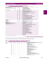
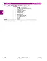
Table 2–4: F60 ORDER CODES (HORIZONTAL UNITS)
F60
-
*
**
- *
*
* - F
**
- H
**
- M
**
- P
**
- U
**
- W/X
**
Full Size Horizontal Mount
Summary of Contents for F60
Page 10: ...x F60 Feeder Protection System GE Multilin TABLE OF CONTENTS ...
Page 30: ...1 20 F60 Feeder Protection System GE Multilin 1 5 USING THE RELAY 1 GETTING STARTED 1 ...
Page 138: ...4 28 F60 Feeder Protection System GE Multilin 4 2 FACEPLATE INTERFACE 4 HUMAN INTERFACES 4 ...
Page 454: ...5 316 F60 Feeder Protection System GE Multilin 5 10 TESTING 5 SETTINGS 5 ...
Page 500: ...7 14 F60 Feeder Protection System GE Multilin 7 1 COMMANDS 7 COMMANDS AND TARGETS 7 ...
Page 508: ...8 8 F60 Feeder Protection System GE Multilin 8 2 FAULT LOCATOR 8 THEORY OF OPERATION 8 ...
Page 522: ...10 12 F60 Feeder Protection System GE Multilin 10 6 DISPOSAL 10 MAINTENANCE 10 ...
Page 660: ...B 116 F60 Feeder Protection System GE Multilin B 4 MEMORY MAPPING APPENDIX B B ...
Page 706: ...E 10 F60 Feeder Protection System GE Multilin E 1 IEC 60870 5 104 APPENDIX E E ...
Page 718: ...F 12 F60 Feeder Protection System GE Multilin F 2 DNP POINT LISTS APPENDIX F F ...
Page 728: ...H 8 F60 Feeder Protection System GE Multilin H 2 ABBREVIATIONS APPENDIX H H Z Impedance Zone ...
Page 730: ...H 10 F60 Feeder Protection System GE Multilin H 3 WARRANTY APPENDIX H H ...


