


GE Multilin
F60 Feeder Protection System
3-13
3 HARDWARE
3.2 WIRING
3
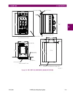
Figure 3–13: ZERO-SEQUENCE CORE BALANCE CT INSTALLATION
The phase voltage channels are used for most metering and protection purposes. The auxiliary voltage channel is used as
input for the synchrocheck and volts-per-hertz features.
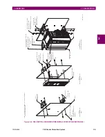
Substitute the tilde “~” symbol with the slot position of the module in the following figure.
Figure 3–14: CT/VT MODULE WIRING
Ground connection to neutral
must be on the source side
UNSHIELDED CABLE
LOAD
A
B
C
N
G
Ground
outside CT
Source
LOAD
SHIELDED CABLE
996630A6.CDR
A
B
C
Source
To ground;
must be on
load side
Stress cone
shields
NOTE
~
~
~
~
~
~
~
~
~
~
~
~
~
~
~
~
~
~
~
~
1a
1b
1c
2a
2b
2c
3a
4a
5a
6a
7a
8a
3b
4b
5c
6c
7c
8c
3c
4c
Current inputs
8F and 8G modules (4 CTs and 4 VTs)
Voltage inputs
VA
VB
VC
VX
VA
VB
VC
VX
IA
IC
IB
IG
IA5
IC5
IB5
IG5
IA1
IC1
IB1
IG1
Current inputs
Not used
8Z module (used for high-impedance fault detection)
~
~
~
~
~
~
~
~
~
~
~
~
1a
1b
1c
2a
2b
2c
3a
4a
3b
4b
3c
4c
IA
IC
IB
IG
IA5
IC5
IB5
IG5
IA1
IC1
IB1
IG1
~
~
~
~
~
~
~
~
~
~
~
~
~
~
~
~
~
~
~
~
~
~
~
~
1a
5a
1b
5b
1c
5c
2a
6a
2b
6b
2c
6c
3a
7a
4a
8a
3b
7b
4b
8b
3c
7c
4c
8c
Current inputs
8H and 8J modules (8 CTs)
IA
IA
IC
IC
IB
IB
IG
IG
IA5
IA5
IC5
IC5
IB5
IB5
IG5
IG5
IA1
IA1
IC1
IC1
IB1
IB1
IG1
IG1
842769A1.CDR
Summary of Contents for F60
Page 10: ...x F60 Feeder Protection System GE Multilin TABLE OF CONTENTS ...
Page 30: ...1 20 F60 Feeder Protection System GE Multilin 1 5 USING THE RELAY 1 GETTING STARTED 1 ...
Page 138: ...4 28 F60 Feeder Protection System GE Multilin 4 2 FACEPLATE INTERFACE 4 HUMAN INTERFACES 4 ...
Page 454: ...5 316 F60 Feeder Protection System GE Multilin 5 10 TESTING 5 SETTINGS 5 ...
Page 500: ...7 14 F60 Feeder Protection System GE Multilin 7 1 COMMANDS 7 COMMANDS AND TARGETS 7 ...
Page 508: ...8 8 F60 Feeder Protection System GE Multilin 8 2 FAULT LOCATOR 8 THEORY OF OPERATION 8 ...
Page 522: ...10 12 F60 Feeder Protection System GE Multilin 10 6 DISPOSAL 10 MAINTENANCE 10 ...
Page 660: ...B 116 F60 Feeder Protection System GE Multilin B 4 MEMORY MAPPING APPENDIX B B ...
Page 706: ...E 10 F60 Feeder Protection System GE Multilin E 1 IEC 60870 5 104 APPENDIX E E ...
Page 718: ...F 12 F60 Feeder Protection System GE Multilin F 2 DNP POINT LISTS APPENDIX F F ...
Page 728: ...H 8 F60 Feeder Protection System GE Multilin H 2 ABBREVIATIONS APPENDIX H H Z Impedance Zone ...
Page 730: ...H 10 F60 Feeder Protection System GE Multilin H 3 WARRANTY APPENDIX H H ...


