


4-22
F60 Feeder Protection System
GE Multilin
4.2 FACEPLATE INTERFACE
4 HUMAN INTERFACES
4
4.
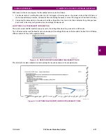
Slide the new user-programmable pushbutton label inside the pocket until the text is properly aligned with the buttons,
as shown below.
4.2.4 DISPLAY
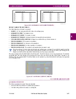
All messages are displayed on a backlit liquid crystal display (LCD) to make them visible under poor lighting conditions.
While the keypad and display are not actively being used, the display defaults to user-defined messages. Any high-priority
event-driven message automatically overrides the default message and appears on the display.
Settings files conversion from previous firmware versions is supported.
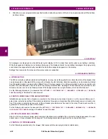
4.2.5 BREAKER CONTROL
a) INTRODUCTION
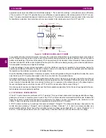
The F60 can interface with associated circuit breakers. In many cases the application monitors the state of the breaker, that
can be presented on faceplate LEDs, along with a breaker trouble indication. Breaker operations can be manually initiated
from faceplate keypad or automatically initiated from a FlexLogic operand. A setting is provided to assign names to each
breaker; this user-assigned name is used for the display of related flash messages. These features are provided for two
breakers; the user can use only those portions of the design relevant to a single breaker, which must be breaker 1.
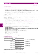
For the following discussion it is assumed the
SETTINGS
SYSTEM SETUP
BREAKERS
BREAKER 1(2)
BREAKER
FUNCTION
setting is "Enabled" for each breaker.
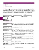
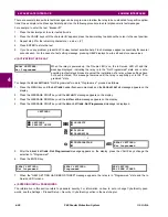
b) CONTROL MODE SELECTION AND MONITORING
Installations can require that a breaker is operated in the three-pole only mode (3-pole), or in the one and three-pole (1-
pole) mode, selected by setting. If the mode is selected as three-pole, a single input tracks the breaker open or closed posi-
tion. If the mode is selected as one-pole, all three breaker pole states must be input to the relay. These inputs must be in
agreement to indicate the position of the breaker.
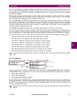
For the following discussion it is assumed the
SETTINGS
SYSTEM SETUP
BREAKERS
BREAKER 1(2)
BREAKER
1(2) PUSH BUTTON CONTROL
setting is “Enabled” for each breaker.
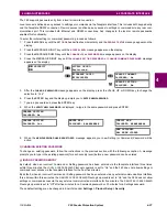
c) FACEPLATE (USER KEY) CONTROL
After the 30 minute interval during which command functions are permitted after a correct command password, the user
cannot open or close a breaker via the keypad. The following discussions begin from the not-permitted state.
d) CONTROL OF TWO BREAKERS
For the following example setup, the
(Name)
field represents the user-programmed variable name.
Summary of Contents for F60
Page 10: ...x F60 Feeder Protection System GE Multilin TABLE OF CONTENTS ...
Page 30: ...1 20 F60 Feeder Protection System GE Multilin 1 5 USING THE RELAY 1 GETTING STARTED 1 ...
Page 138: ...4 28 F60 Feeder Protection System GE Multilin 4 2 FACEPLATE INTERFACE 4 HUMAN INTERFACES 4 ...
Page 454: ...5 316 F60 Feeder Protection System GE Multilin 5 10 TESTING 5 SETTINGS 5 ...
Page 500: ...7 14 F60 Feeder Protection System GE Multilin 7 1 COMMANDS 7 COMMANDS AND TARGETS 7 ...
Page 508: ...8 8 F60 Feeder Protection System GE Multilin 8 2 FAULT LOCATOR 8 THEORY OF OPERATION 8 ...
Page 522: ...10 12 F60 Feeder Protection System GE Multilin 10 6 DISPOSAL 10 MAINTENANCE 10 ...
Page 660: ...B 116 F60 Feeder Protection System GE Multilin B 4 MEMORY MAPPING APPENDIX B B ...
Page 706: ...E 10 F60 Feeder Protection System GE Multilin E 1 IEC 60870 5 104 APPENDIX E E ...
Page 718: ...F 12 F60 Feeder Protection System GE Multilin F 2 DNP POINT LISTS APPENDIX F F ...
Page 728: ...H 8 F60 Feeder Protection System GE Multilin H 2 ABBREVIATIONS APPENDIX H H Z Impedance Zone ...
Page 730: ...H 10 F60 Feeder Protection System GE Multilin H 3 WARRANTY APPENDIX H H ...


