


GE Multilin
F60 Feeder Protection System
5-201
5 SETTINGS
5.6 GROUPED ELEMENTS
5
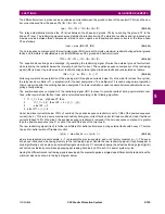
EXAMPLE 5: INTERNAL LOW-CURRENT, HIGH-LOAD SINGLE-LINE-TO-GROUND FAULT WITH NO FEED FROM
THE GROUND
Given the following inputs: IA = 1.10 pu
∠
0°, IB = 1.0 pu
∠
–120°, IC = 1.0 pu
∠
120°, and IG = 0.0 pu
∠
0°
The relay calculates the following values:
I_0 = 0.033 pu
∠
0°, I_2 = 0.033 pu
∠
0°, and I_1 = 1.033 pu
∠
0°
Igd = abs(3
×
0.0333 + 0.0) = 0.10 pu, IR0 = abs(3
×
0.033 – (0.0)) = 0.10 pu, IR2 = 3
×
0.033 = 0.10 pu,
IR1 = 1.033 / 8 = 0.1292 pu, and Igr = 0.1292 pu
Despite very low fault current level the differential current is above 75% of the restraining current.
EXAMPLE 6: INTERNAL HIGH-CURRENT SINGLE-LINE-TO-GROUND FAULT WITH NO FEED FROM THE GROUND
Given the following inputs: IA = 10 pu
∠
0°, IB = 0 pu, IC = 0 pu, and IG = 0 pu
The relay calculates the following values:
I_0 = 3.3 pu
∠
0°, I_2 = 3.3 pu
∠
0°, and I_1 = 3.3 pu
∠
0°
Igd = abs(3
×
3.3 + 0.0) = 10 pu, IR0 = abs(3
×
3.3 – (0.0)) = 10 pu, IR2 = 3
×
3.3 = 10 pu, IR1 = 3
×
(3.33 – 3.33) = 0
pu, and Igr = 10 pu
The differential current is 100% of the restraining current.
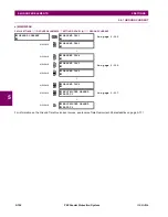
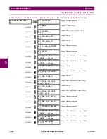
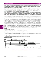
5.6.8 NEGATIVE-SEQUENCE CURRENT
a) MAIN MENU
PATH: SETTINGS
GROUPED ELEMENTS
SETTING GROUP 1(6)
NEGATIVE SEQUENCE CURRENT
For additional information on the negative sequence time overcurrent curves, refer to the
Inverse Time Overcurrent Curves
section earlier.
NEGATIVE SEQUENCE
CURRENT
NEG SEQ TOC1
MESSAGE
NEG SEQ TOC2
MESSAGE
NEG SEQ IOC1
MESSAGE
NEG SEQ IOC2
MESSAGE
NEG SEQ DIR OC1
MESSAGE
NEG SEQ DIR OC2
Summary of Contents for F60
Page 10: ...x F60 Feeder Protection System GE Multilin TABLE OF CONTENTS ...
Page 30: ...1 20 F60 Feeder Protection System GE Multilin 1 5 USING THE RELAY 1 GETTING STARTED 1 ...
Page 138: ...4 28 F60 Feeder Protection System GE Multilin 4 2 FACEPLATE INTERFACE 4 HUMAN INTERFACES 4 ...
Page 454: ...5 316 F60 Feeder Protection System GE Multilin 5 10 TESTING 5 SETTINGS 5 ...
Page 500: ...7 14 F60 Feeder Protection System GE Multilin 7 1 COMMANDS 7 COMMANDS AND TARGETS 7 ...
Page 508: ...8 8 F60 Feeder Protection System GE Multilin 8 2 FAULT LOCATOR 8 THEORY OF OPERATION 8 ...
Page 522: ...10 12 F60 Feeder Protection System GE Multilin 10 6 DISPOSAL 10 MAINTENANCE 10 ...
Page 660: ...B 116 F60 Feeder Protection System GE Multilin B 4 MEMORY MAPPING APPENDIX B B ...
Page 706: ...E 10 F60 Feeder Protection System GE Multilin E 1 IEC 60870 5 104 APPENDIX E E ...
Page 718: ...F 12 F60 Feeder Protection System GE Multilin F 2 DNP POINT LISTS APPENDIX F F ...
Page 728: ...H 8 F60 Feeder Protection System GE Multilin H 2 ABBREVIATIONS APPENDIX H H Z Impedance Zone ...
Page 730: ...H 10 F60 Feeder Protection System GE Multilin H 3 WARRANTY APPENDIX H H ...


