


GE Multilin
F60 Feeder Protection System
5-161
5 SETTINGS
5.5 FLEXLOGIC
5
8.
The logic should always be tested after it is loaded into the relay, in the same fashion as has been used in the past.
Testing can be simplified by placing an "END" operator within the overall set of FlexLogic equations. The equations will
then only be evaluated up to the first "END" operator.
The "On" and "Off" operands can be placed in an equation to establish a known set of conditions for test purposes, and
the "INSERT" and "DELETE" commands can be used to modify equations.
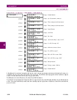
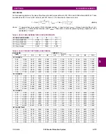
5.5.5 FLEXLOGIC EQUATION EDITOR
PATH: SETTINGS
FLEXLOGIC
FLEXLOGIC EQUATION EDITOR
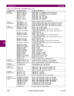
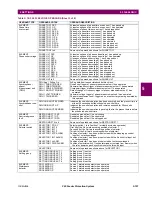
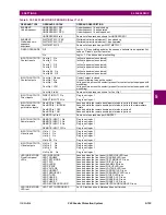
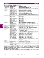
There are 512 FlexLogic entries available, numbered from 1 to 512, with default END entry settings. If a "Disabled" Element
is selected as a FlexLogic entry, the associated state flag will never be set to ‘1’. The ‘+/–‘ key may be used when editing
FlexLogic equations from the keypad to quickly scan through the major parameter types.
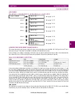
5.5.6 FLEXLOGIC TIMERS
PATH: SETTINGS
FLEXLOGIC
FLEXLOGIC TIMERS
FLEXLOGIC TIMER 1(32)
There are 32 identical FlexLogic timers available. These timers can be used as operators for FlexLogic equations.
•
TIMER 1 TYPE:
This setting is used to select the time measuring unit.
•
TIMER 1 PICKUP DELAY:
Sets the time delay to pickup. If a pickup delay is not required, set this function to "0".
•
TIMER 1 DROPOUT DELAY:
Sets the time delay to dropout. If a dropout delay is not required, set this function to "0".
FLEXLOGIC
EQUATION EDITOR
FLEXLOGIC ENTRY
1:
END
Range: FlexLogic operands
MESSAGE
FLEXLOGIC ENTRY
2:
END
Range: FlexLogic operands
↓
MESSAGE
FLEXLOGIC ENTRY 512:
END
Range: FlexLogic operands
FLEXLOGIC
TIMER 1
TIMER 1
TYPE: millisecond
Range: millisecond, second, minute
MESSAGE
TIMER 1
PICKUP
DELAY: 0
Range: 0 to 60000 in steps of 1
MESSAGE
TIMER 1
DROPOUT
DELAY: 0
Range: 0 to 60000 in steps of 1
Summary of Contents for F60
Page 10: ...x F60 Feeder Protection System GE Multilin TABLE OF CONTENTS ...
Page 30: ...1 20 F60 Feeder Protection System GE Multilin 1 5 USING THE RELAY 1 GETTING STARTED 1 ...
Page 138: ...4 28 F60 Feeder Protection System GE Multilin 4 2 FACEPLATE INTERFACE 4 HUMAN INTERFACES 4 ...
Page 454: ...5 316 F60 Feeder Protection System GE Multilin 5 10 TESTING 5 SETTINGS 5 ...
Page 500: ...7 14 F60 Feeder Protection System GE Multilin 7 1 COMMANDS 7 COMMANDS AND TARGETS 7 ...
Page 508: ...8 8 F60 Feeder Protection System GE Multilin 8 2 FAULT LOCATOR 8 THEORY OF OPERATION 8 ...
Page 522: ...10 12 F60 Feeder Protection System GE Multilin 10 6 DISPOSAL 10 MAINTENANCE 10 ...
Page 660: ...B 116 F60 Feeder Protection System GE Multilin B 4 MEMORY MAPPING APPENDIX B B ...
Page 706: ...E 10 F60 Feeder Protection System GE Multilin E 1 IEC 60870 5 104 APPENDIX E E ...
Page 718: ...F 12 F60 Feeder Protection System GE Multilin F 2 DNP POINT LISTS APPENDIX F F ...
Page 728: ...H 8 F60 Feeder Protection System GE Multilin H 2 ABBREVIATIONS APPENDIX H H Z Impedance Zone ...
Page 730: ...H 10 F60 Feeder Protection System GE Multilin H 3 WARRANTY APPENDIX H H ...


