Chapter 5
5-24
5.4.4 Reader Controller PCB
5.4.4.1 Points to Note Before Replacing the Reader
Controller PCB
0019-4766
iR3225 / iR3225N / iR3235 / iR3235N / iR3245 / iR3245N
5.4.4.2 Removing the Reader Controller PCB
0019-4772
iR3225 / iR3225N / iR3235 / iR3235N / iR3245 / iR3245N
1)Remove the ADF communication cable (ADF only).
2)Remove the platen board cover or the ADF.
3)Remove the reader rear cover
4)Remove the LED driver PCB.
-1 screw [2]
-J4 connector [4]
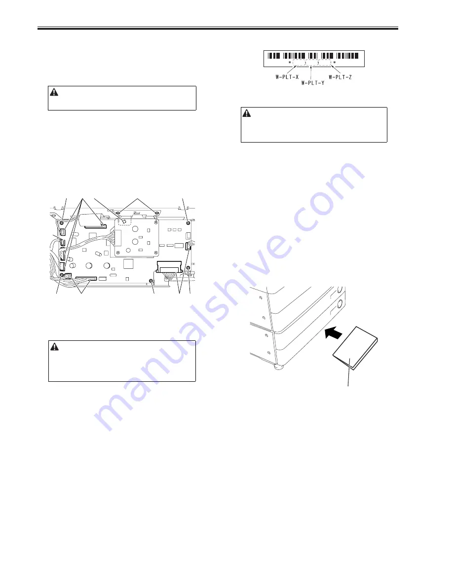
5)Remove the reader controller PCB.
-6 screws [3]
-7 connectors [1]
F-5-43
5.4.4.3 After Replacing the Reader Controller PCB
0019-5735
iR3225 / iR3225N / iR3235 / iR3235N / iR3245 / iR3245N
1. Adjustment related to the reader unit
1)Using SST, download the latest system software (R-CON).
2)Select the following service mode; COPIER > FUNCTION > CLEAR >
R-CON,
hold down OK, and then execute RAM clear. After that, turn off/on the
main power switch.
3)Enter the values of the following items in service mode.
a. Value on the service label (inside of the reader left cover)
a-1.Adjusting the CCD reading position (in fixed reading)
COPIER>ADJUST>ADJ-XY>ADJ-X
a-2.Adjusting the position in main scanning direction (in fixed reading)
COPIER>ADJUST>ADJ-XY>ADJ-Y
a-3.Adjusting the shading position (in fixed reading)
COPIER>ADJUST>ADJ-XY>ADJ-S
a-4.Value of MTF in main scanning direction
COPIER>ADJUST>CCD>MTF3-M1/M2/M3/M4/M5/M6/M7/M8/
M9
After that, finalize the setting in the following mode.
COPIER>ADJUST>CCD>CCD-CHNG
a-5.Value of copyboard sub scanning magnification adjustment
COPIER>ADJUST>ADJ-XY>ADJ-X-MAG
a-6.Value of Pascal offset (black) adjustment
COPIER>ADJUST>PASCAL>OFST-P-K
a-7.Value of 100% color displacement correction
COPIER>ADJUST>CCD>100-RG/100-GB
a-8.Value of 50% color displacement correction
COPIER>ADJUST>CCD>50-RG/50-GB
b.Entering the data of the standard white plate
COPIER>ADJUST>CCD>W-PLT-X/Y/Z
F-5-44
2. Adjustment related to ADF
1)Enter the value of the output P-PRINT in the following item in service
mode.
a. Adjusting the position in main scanning direction (in stream reading)
COPIER>ADJUST>ADJ-XY>ADJ-Y-DF
b. Adjusting the trailing edge registration
FEEDER>ADJUST>DOCST
c. Adjusting magnification
FEEDER>ADJUST>LA-SPEED
2)Execute adjustment using the following items.
a. Adjusting the tray width
FEEDER>FUNCTION>TRY-A4
FEEDER>FUNCTION>TRY-A5R
FEEDER>FUNCTION>TRY-LTR
FEEDER>FUNCTION>TRY-LTRR
b. Adjusting the CCD reading position (in stream reading)
COPIER>FUNCTION>INSTALL>STRD-POS
c. Adjusting the white level
COPIER>FUNCTION>CCD>DF-WLVL1(black and white)
COPIER>FUNCTION>CCD>DF-WLVL2(black and white)
COPIER>FUNCTION>CCD>DF-WLVL3(color)
COPIER>FUNCTION>CCD>DF-WLVL4(color)
After completing the above adjustments, keep the output P-PRINT [1] in the
service book case and dispose the old P-PRINT
F-5-45
Be sure to output P-PRINT in service mode before replacement.
COPIER>FUNCTION>MISC-P>P-PRINT
Be sure to output the latest P-PRINT before replacing the reader controller
PCB.
-In the case of clearing RAM for the reader controller without replacing the
PCB, the following adjustment is unnecessary if uploading the R-CON
backup data using SST and downloading the data after clearing RAM.
[2]
[3]
[1]
[3]
[3]
[3]
[3]
[3]
[1]
[1]
[4]
In the equipment, the service data related to ADF is stored in RAM of the
reader controller.
Therefore, adjustment for ADF is necessary when replacing the reader
controller and clearing RAM
8 2 0 6 8 6 6 7 9 3 4 9
[1]
Summary of Contents for iR3245
Page 1: ...Jul 3 2008 Service Manual iR3245 3235 3230 3225 Series...
Page 2: ......
Page 6: ......
Page 25: ...Chapter 1 Introduction...
Page 26: ......
Page 28: ......
Page 64: ......
Page 65: ...Chapter 2 Installation...
Page 66: ......
Page 120: ......
Page 121: ...Chapter 3 Basic Operation...
Page 122: ......
Page 124: ......
Page 128: ......
Page 129: ...Chapter 4 Main Controller...
Page 130: ......
Page 132: ......
Page 134: ...Chapter 4 4 2 F 4 1 1 5 8 9 11 14 12 3 4 10 2 13 7 15 16 17...
Page 152: ......
Page 153: ...Chapter 5 Original Exposure System...
Page 154: ......
Page 184: ......
Page 185: ...Chapter 6 Laser Exposure...
Page 186: ......
Page 188: ......
Page 197: ...Chapter 7 Image Formation...
Page 198: ......
Page 227: ...Chapter 8 Pickup Feeding System...
Page 228: ......
Page 232: ......
Page 244: ...Chapter 8 8 12 For iR3245 3235 3230 F 8 14 1 2 3 4...
Page 261: ...Chapter 8 8 29 10 11 12 13 14 3 1 2 4 5 4 4 1 2 3 5 4 1 2 3 5 5 4 1 2 3 5 4 1 2 3 5...
Page 278: ......
Page 279: ...Chapter 9 Fixing System...
Page 280: ......
Page 282: ......
Page 297: ...Chapter 10 External and Controls...
Page 298: ......
Page 302: ......
Page 315: ...Chapter 10 10 13 2 Uncheck SNMP Status Enabled F 10 11...
Page 342: ......
Page 343: ...Chapter 11 MEAP...
Page 344: ......
Page 346: ......
Page 397: ...Chapter 12 e maintenance imageWARE Remote...
Page 398: ......
Page 400: ......
Page 408: ......
Page 409: ...Chapter 13 Maintenance and Inspection...
Page 410: ......
Page 412: ......
Page 424: ...Chapter 13 13 12...
Page 425: ...Chapter 14 Standards and Adjustments...
Page 426: ......
Page 428: ......
Page 436: ......
Page 437: ...Chapter 15 Correcting Faulty Images...
Page 438: ......
Page 440: ......
Page 465: ...Chapter 16 Self Diagnosis...
Page 466: ......
Page 468: ......
Page 493: ...Chapter 17 Service Mode...
Page 494: ......
Page 498: ......
Page 690: ......
Page 691: ...Chapter 18 Upgrading...
Page 692: ......
Page 694: ......
Page 738: ...Chapter 18 18 44...
Page 739: ...Chapter 19 Service Tools...
Page 740: ......
Page 742: ......
Page 744: ......
Page 745: ...Jul 3 2008...
Page 746: ......


