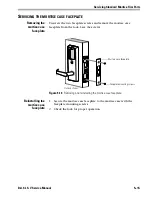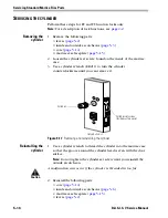
Servicing Standard Mortise Trim Parts
5–2
B.A.S.I.S. V Service Manual
S
ERVICING
THE
LEVERS
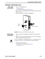
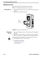
Removing the levers
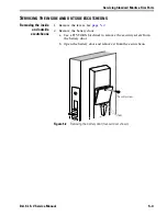
1. Remove the set screw cap and use a 1/8
″
Allen wrench to remove
the set screw from the inside lever.
2. Remove the inside lever, then the outside lever and spindle
assembly from the door.
Reinstalling the
levers
1. Unscrew the inside spindle one full turn to allow the spindles to
turn freely.
2. With the handle pointing toward the door hinges, insert the outside
lever and spindles assembly into the lock from the outside of the
door.
3. Slide the inside lever onto the inside spindle and secure it with the
set screw.
4.
If you removed the escutcheons from the door
, make sure that the
core is positioned properly in the outside escutcheon (EV and FV
only), the escutcheons are aligned properly on the door, and tighten
the escutcheon mounting screws.
Note:
For a description of lock functions, see
page 2–2
.
5. Turn the levers to check that they operate smoothly.
Figure 5.1
Removing and reinstalling the levers
Location of set screw
Inside of door
Spindles
Outside of door
Summary of Contents for B.A.S.I.S. V
Page 1: ...SERVICE MANUAL SERVICE MANUAL ...
Page 16: ...Figures xvi B A S I S V Service Manual ...
Page 48: ...Standard Functions and Parts 2 24 B A S I S V Service Manual ...
Page 66: ...Exit Hardware Trim Functions and Parts 3 18 B A S I S V Service Manual ...
Page 78: ...Shared Standard and Exit Hardware Trim Parts 4 12 B A S I S V Service Manual ...
Page 114: ...Servicing Standard Mortise Case Parts 6 20 B A S I S V Service Manual ...
Page 206: ...Servicing Exit Hardware Trim Escutcheon Parts 10 32 B A S I S V Service Manual ...
Page 238: ...Troubleshooting 12 12 B A S I S V Service Manual ...
Page 242: ...Lock History Event Types A 4 B A S I S V Service Manual ...
Page 244: ...Installation Instructions B 2 B A S I S V Service Manual ...


