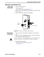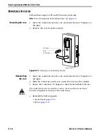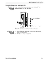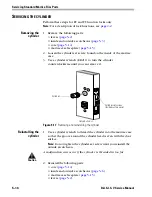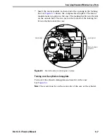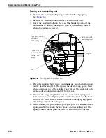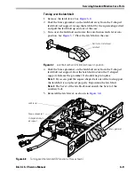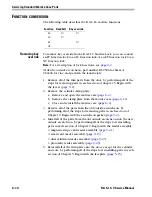
Servicing Standard Mortise Case Parts
6–4
B.A.S.I.S. V Service Manual
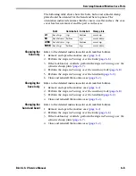
The following diagram and table show which components need to be
turned over when changing the hand and bevel. See the section that
follows for instructions.
■
B represents the latchbolt and auxiliary bolt
■
H represents the hubs
■
C represents the cylinder clamp plate assembly.
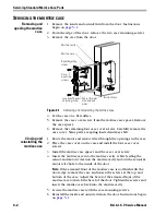
Figure 6.3
Overview of changing the hand and bevel (FV function, LH case shown)
Outside hub
Inside hub
Latchbolt
Cylinder clamp plate
Auxiliary bolt
LH
RH
LHRB
RHRB
LH
B/H/C
B
H/C
RH
B/H/C
H/C
B
LHRB
B
H/C
B/H/C
RHRB
H/C
B
B/H/C
Summary of Contents for B.A.S.I.S. V
Page 1: ...SERVICE MANUAL SERVICE MANUAL ...
Page 16: ...Figures xvi B A S I S V Service Manual ...
Page 48: ...Standard Functions and Parts 2 24 B A S I S V Service Manual ...
Page 66: ...Exit Hardware Trim Functions and Parts 3 18 B A S I S V Service Manual ...
Page 78: ...Shared Standard and Exit Hardware Trim Parts 4 12 B A S I S V Service Manual ...
Page 114: ...Servicing Standard Mortise Case Parts 6 20 B A S I S V Service Manual ...
Page 206: ...Servicing Exit Hardware Trim Escutcheon Parts 10 32 B A S I S V Service Manual ...
Page 238: ...Troubleshooting 12 12 B A S I S V Service Manual ...
Page 242: ...Lock History Event Types A 4 B A S I S V Service Manual ...
Page 244: ...Installation Instructions B 2 B A S I S V Service Manual ...

