Servicing Standard Outside Escutcheon Parts
9–12
B.A.S.I.S. V Service Manual
Removing the
smart card control
electronics board
1. Remove the following parts:
■
inside and outside escutcheons. For mortise lock instructions,
see
page 5–3
. For cylindrical lock instructions, see
page 7–5
.
■
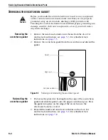
escutcheon gasket (
page 9–2
)
■
harness clamp (
page 9–4
)
■
upgrade cable (
page 9–5
)
■
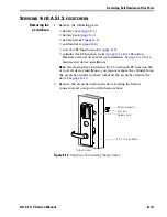
sensor harness (
page 9–6
)
■
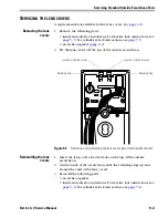
primary harness (step 2,
page 9–7
).
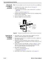
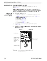
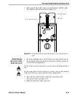
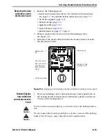
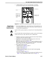
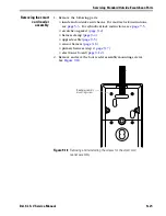
2. Remove and save the electronics board mounting screws.
See
Figure 9.10
.
3. Flip up the control electronics board.
Figure 9.10
Removing and reinstalling the smart card control electronics board
Retaining ring
Retaining ring
Electronics board
Outside escutcheon
Electronics board
mounting screw
Electronics board
mounting screw
(used for harness
clamp)
Summary of Contents for B.A.S.I.S. V
Page 1: ...SERVICE MANUAL SERVICE MANUAL ...
Page 16: ...Figures xvi B A S I S V Service Manual ...
Page 48: ...Standard Functions and Parts 2 24 B A S I S V Service Manual ...
Page 66: ...Exit Hardware Trim Functions and Parts 3 18 B A S I S V Service Manual ...
Page 78: ...Shared Standard and Exit Hardware Trim Parts 4 12 B A S I S V Service Manual ...
Page 114: ...Servicing Standard Mortise Case Parts 6 20 B A S I S V Service Manual ...
Page 206: ...Servicing Exit Hardware Trim Escutcheon Parts 10 32 B A S I S V Service Manual ...
Page 238: ...Troubleshooting 12 12 B A S I S V Service Manual ...
Page 242: ...Lock History Event Types A 4 B A S I S V Service Manual ...
Page 244: ...Installation Instructions B 2 B A S I S V Service Manual ...

