BEST ACCESS SYSTEMS
Indianapolis, Indiana
1
Planning the installation
Contents
These installation instructions describe how to install your
B.A.S.I.S.® G (35HG) or B.A.S.I.S. V (35HBV) Mortise Lock.
The following topics are covered.
†
Planning the installation
................................................ 1
Preparing the door and door jamb
................................ 2
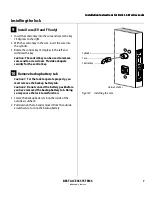
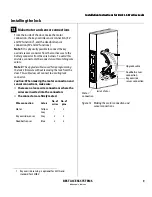
Installing the lock
............................................................ 5
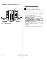
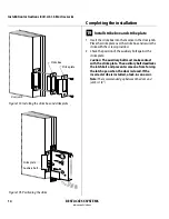
Completing the installation
..........................................11
Site survey
Use the following survey to record information about the
installation site.
Lock information
Lock function:
❑
EV–Latch with key override
❑
With key override sensing
‡
❑
FV–Deadbolt with key override
❑
With key override sensing
‡
❑
LV–Deadbolt without key override
❑
NV–Latch without key override
Door information
Door handing and bevel:
❑
Left hand (LH)
❑
Left hand, reverse bevel (LHRB)
❑
Right hand (RH)
❑
Right hand, reverse bevel (RHRB)
Door thickness: inches (1 3/4
″
to 3
″ )
Environment information
Ambient temperature:
❑
Is within specifications. See the tables below.
This product meets the following Locked Door Outdoor
test requirements for ANSI/BHMA 156.25:
† The Best Access Systems logo and B.A.S.I.S. are
registered trademarks of Best Lock Corporation.
‡ Key override sensing is optional for 35HG and
standard for 35HBV.
Side of door
Range
Inside
+66°F to +74°F (+19°C to +23°C)
Outside
–31°F to +151°F (–35°C to +66°C)
This product meets the following Full Indoor test
requirements for ANSI/BHMA 156.25:
Components checklist
Use the following checklist to make sure that you have the
items necessary to install your B.A.S.I.S. Mortise Lock.
Components provided in the box:
❑
Mortise case assembly
❑
Mortise case faceplate
❑
Inside escutcheon assembly
❑
Battery compartment door
❑
Battery pack
❑
Outside escutcheon assembly
❑
Inside and outside mounting plates
❑
Inside lever
❑
Outside lever & spindle assembly
❑
Cylinder assembly (for EV and FV functions only)
❑
Screw package
❑
Plastic bushing package
❑
Trim hole insert package
❑
Escutcheon screw package
❑
Strike
❑
Strike box
❑
Bar code ID sticker (for your records)
❑
Temporary operator card
❑
Installation template and instructions
Other components:
❑
Core (for EV and FV functions only)
❑
Control key (for EV and FV functions only)
Special tools checklist
Use the following checklist to make sure that you have the
special tools necessary to install your B.A.S.I.S. Mortise Lock.
❑
T15 TORX® bit driver
††
❑
ED211 cylinder wrench (for EV and FV functions only)
Side of door
Range
Inside and outside
+32°F to +120°F (0°C to +42°C)
†† TORX is a registered trademark of the Camcar
Division of Textron.
Installation Instructions for
B.A.S.I.S. Mortise Locks
Summary of Contents for B.A.S.I.S. V
Page 1: ...SERVICE MANUAL SERVICE MANUAL ...
Page 16: ...Figures xvi B A S I S V Service Manual ...
Page 48: ...Standard Functions and Parts 2 24 B A S I S V Service Manual ...
Page 66: ...Exit Hardware Trim Functions and Parts 3 18 B A S I S V Service Manual ...
Page 78: ...Shared Standard and Exit Hardware Trim Parts 4 12 B A S I S V Service Manual ...
Page 114: ...Servicing Standard Mortise Case Parts 6 20 B A S I S V Service Manual ...
Page 206: ...Servicing Exit Hardware Trim Escutcheon Parts 10 32 B A S I S V Service Manual ...
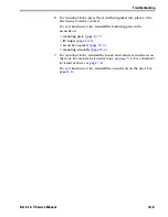
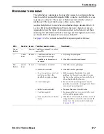
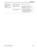
Page 238: ...Troubleshooting 12 12 B A S I S V Service Manual ...
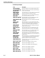
Page 242: ...Lock History Event Types A 4 B A S I S V Service Manual ...
Page 244: ...Installation Instructions B 2 B A S I S V Service Manual ...

