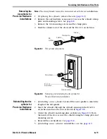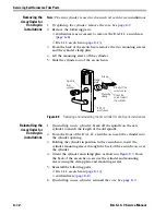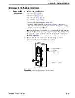
Servicing Exit Hardware Trim Parts
8–10
B.A.S.I.S. V Service Manual
S
ERVICING
THE
CYLINDER
Perform these steps for EV function locks only.
Note:
For a description of lock functions, see
page 3–2
.
Removing the
mortise cylinder
1. Remove the core. See
page 8–9
.
2. Insert a cylinder wrench (ED211) into the cylinder and unscrew the
cylinder from the mortise case.
3. Slide the cylinder and cylinder ring (if present) out of the door and
escutcheon.
Reinstalling the
mortise cylinder
1.
For doors less than 2
″
in thickness
, place the cylinder ring provided
on the cylinder.
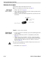
2. Rotate the cylinder cam to the 12 o’clock position, as shown in
Figure 8.6
.
3. Using a cylinder wrench (ED211), insert the cylinder through the
cylinder opening in the B.A.S.I.S. escutcheon and screw the cylinder
into the mortise case. Make sure that the cylinder is oriented as
shown in
Figure 8.6
.
Caution
Do not screw the cylinder in too tightly. Doing so may cause you or
someone else to be locked out.
4. Reinstall the core. See
page 8–9
.
Figure 8.6
Mortise cylinder components
Mortise cylinder
Cam in 12 o’clock
position
View of the back of
the cylinder
Location of throw pins
Summary of Contents for B.A.S.I.S. V
Page 1: ...SERVICE MANUAL SERVICE MANUAL ...
Page 16: ...Figures xvi B A S I S V Service Manual ...
Page 48: ...Standard Functions and Parts 2 24 B A S I S V Service Manual ...
Page 66: ...Exit Hardware Trim Functions and Parts 3 18 B A S I S V Service Manual ...
Page 78: ...Shared Standard and Exit Hardware Trim Parts 4 12 B A S I S V Service Manual ...
Page 114: ...Servicing Standard Mortise Case Parts 6 20 B A S I S V Service Manual ...
Page 206: ...Servicing Exit Hardware Trim Escutcheon Parts 10 32 B A S I S V Service Manual ...
Page 238: ...Troubleshooting 12 12 B A S I S V Service Manual ...
Page 242: ...Lock History Event Types A 4 B A S I S V Service Manual ...
Page 244: ...Installation Instructions B 2 B A S I S V Service Manual ...

