Servicing Standard Mortise Case Parts
B.A.S.I.S. V Service Manual
6–9
Turning over the latchbolt
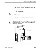
1. Remove the latch lever. See
Figure 6.8
2. Slide the brass grommet on the latchbolt away from the U-shaped
latchbolt rod support. Grasp the latchbolt by the square-shaped tail
and pull the latchbolt up and out of the case.
3. Turn over the latchbolt and rotate the anti-friction latch lever into
position. See
Figure 6.7
. Place the latchbolt in the case.
4. Slide the brass grommet on the latchbolt away from the U-shaped
latchbolt rod support. Rest the latchbolt rod into the U-shaped
support. Release the grommet. It should snap into place.
Note 1:
If you can pull the square-shaped tail out of the rod support,
the latchbolt is not placed properly. Reposition the latchbolt.
Note 2:
The bevel of the latchbolt must match the bevel of the
auxiliary bolt.
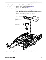
5. Reinstall the latch lever, as shown in
Figure 6.8
.
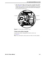
Figure 6.7
Latchbolt with anti-friction latch lever in position
Latchbolt
Anti-friction latch lever
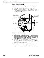
Figure 6.8
Turning over the latchbolt (FV function, LH case shown)
Latch lever
Square-shaped tail
U-shaped latchbolt
rod support
Brass grommet
Summary of Contents for B.A.S.I.S. V
Page 1: ...SERVICE MANUAL SERVICE MANUAL ...
Page 16: ...Figures xvi B A S I S V Service Manual ...
Page 48: ...Standard Functions and Parts 2 24 B A S I S V Service Manual ...
Page 66: ...Exit Hardware Trim Functions and Parts 3 18 B A S I S V Service Manual ...
Page 78: ...Shared Standard and Exit Hardware Trim Parts 4 12 B A S I S V Service Manual ...
Page 114: ...Servicing Standard Mortise Case Parts 6 20 B A S I S V Service Manual ...
Page 206: ...Servicing Exit Hardware Trim Escutcheon Parts 10 32 B A S I S V Service Manual ...
Page 238: ...Troubleshooting 12 12 B A S I S V Service Manual ...
Page 242: ...Lock History Event Types A 4 B A S I S V Service Manual ...
Page 244: ...Installation Instructions B 2 B A S I S V Service Manual ...

