B.A.S.I.S. V Service Manual
xi
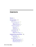
F
IGURES
G
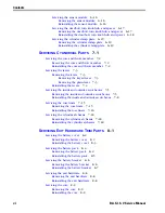
ETTING
S
TARTED
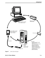
System overview diagram
1–3
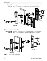
Mortise lock overview diagram
1–4
Cylindrical lock overview diagram
1–4
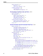
S
TANDARD
F
UNCTIONS
AND
P
ARTS
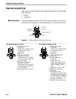
Understanding mortise function drawings
2–2
Understanding the cylindrical function drawing
2–4
Cylindrical chassis diagram
2–21
Other cylindrical lock components
2–23
E
XIT
H
ARDWARE
T
RIM
F
UNCTIONS
AND
P
ARTS
Mortise cylinder and related components diagram
3–15
Rim cylinder and related components diagram
3–16
Levers diagram
3–17
S
HARED
S
TANDARD
AND
E
XIT
H
ARDWARE
T
RIM
P
ARTS
Other system components diagram
4–11
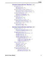
S
ERVICING
S
TANDARD
M
ORTISE
T
RIM
P
ARTS
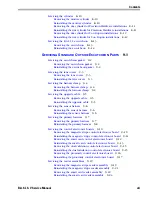
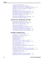
Removing and reinstalling the levers
5–2
Removing the battery door (four-cell door shown)
5–3
Removing the battery pack (four-cell pack shown)
5–4
Removing the inside escutcheon
5–4
Disconnecting the motor connector and sensor connector
5–5
Removing the bushings and trim hole inserts
5–5
Summary of Contents for B.A.S.I.S. V
Page 1: ...SERVICE MANUAL SERVICE MANUAL ...
Page 16: ...Figures xvi B A S I S V Service Manual ...
Page 48: ...Standard Functions and Parts 2 24 B A S I S V Service Manual ...
Page 66: ...Exit Hardware Trim Functions and Parts 3 18 B A S I S V Service Manual ...
Page 78: ...Shared Standard and Exit Hardware Trim Parts 4 12 B A S I S V Service Manual ...
Page 114: ...Servicing Standard Mortise Case Parts 6 20 B A S I S V Service Manual ...
Page 206: ...Servicing Exit Hardware Trim Escutcheon Parts 10 32 B A S I S V Service Manual ...
Page 238: ...Troubleshooting 12 12 B A S I S V Service Manual ...
Page 242: ...Lock History Event Types A 4 B A S I S V Service Manual ...
Page 244: ...Installation Instructions B 2 B A S I S V Service Manual ...


