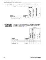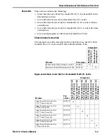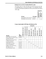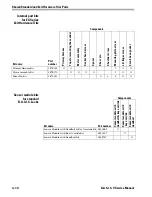
Servicing Standard Mortise Trim Parts
5–8
B.A.S.I.S. V Service Manual
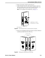
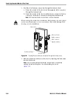
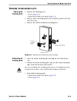
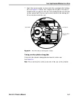
3. Feed the wire harness connectors through the harness hole:
a. From the outside of the door, feed the upgrade cable connector
through the harness hole.
b. From the outside of the door, feed the motor connector, battery
connector, and sensor connectors through the harness hole.
Note:
NV function locks do not have a sensor harness.
Caution
When routing the connectors, make sure the harnesses are not routed
across any sharp edges or over any surface that could damage their
sleeving or wire insulation.
4. Rest the outside escutcheon on the door by inserting the trim studs
into the trim holes.
Note:
You can temporarily install the outside lever to hold the
outside escutcheon in place. See
Reinstalling the levers
(
page 5–2
).
Figure 5.9
Feeding the wire harness connectors through the harness hole
Motor connector
Harness hole
Outside escutcheon
Outside of door
Sensor connectors
Battery connector
Upgrade connector
Summary of Contents for B.A.S.I.S. V
Page 1: ...SERVICE MANUAL SERVICE MANUAL ...
Page 16: ...Figures xvi B A S I S V Service Manual ...
Page 48: ...Standard Functions and Parts 2 24 B A S I S V Service Manual ...
Page 66: ...Exit Hardware Trim Functions and Parts 3 18 B A S I S V Service Manual ...
Page 78: ...Shared Standard and Exit Hardware Trim Parts 4 12 B A S I S V Service Manual ...
Page 114: ...Servicing Standard Mortise Case Parts 6 20 B A S I S V Service Manual ...
Page 206: ...Servicing Exit Hardware Trim Escutcheon Parts 10 32 B A S I S V Service Manual ...
Page 238: ...Troubleshooting 12 12 B A S I S V Service Manual ...
Page 242: ...Lock History Event Types A 4 B A S I S V Service Manual ...
Page 244: ...Installation Instructions B 2 B A S I S V Service Manual ...

