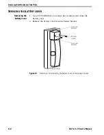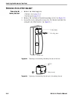
Servicing Cylindrical Parts
7–16
B.A.S.I.S. V Service Manual
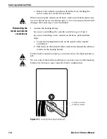
Reinstalling the
rose liners
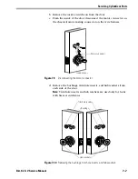
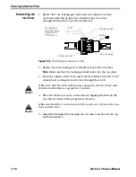
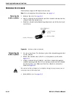
1. Retract the rose locking pin, and rotate the outside rose liner
clockwise until the proper door thickness groove on the
through-bolt stud lines up with the hub face.
2. Release the rose locking pin. It should lock into the rose liner.
Note:
Make sure that the locking pin fully locks into the rose liner.
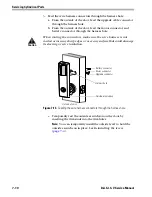
3. From the outside of the door, insert the lock chassis into the 2 1/8
″
chassis hole, routing the motor wire through the notch.
Caution
Make sure that the latch tube prongs engage the chassis frame and
that the latch tailpiece engages the retractor.
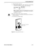
4. Place the inside rose liner on the chassis, aligning the holes in the
rose liner with the holes prepared in the door.
Caution
Make sure that there is clearance for the motor wire between the rose
liner and the door.
5. Install the through-bolts through the rose liner and door in the top
and bottom holes.
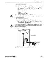
Figure 7.20
Reinstalling the outside rose liner
1
2
″
2 1/4
″
Through-bolt stud
Hub face
Outside rose liner
Rose locking pin
This illustration
shows the chassis
adjusted for a 2
1/4
″
thick door.
Summary of Contents for B.A.S.I.S. V
Page 1: ...SERVICE MANUAL SERVICE MANUAL ...
Page 16: ...Figures xvi B A S I S V Service Manual ...
Page 48: ...Standard Functions and Parts 2 24 B A S I S V Service Manual ...
Page 66: ...Exit Hardware Trim Functions and Parts 3 18 B A S I S V Service Manual ...
Page 78: ...Shared Standard and Exit Hardware Trim Parts 4 12 B A S I S V Service Manual ...
Page 114: ...Servicing Standard Mortise Case Parts 6 20 B A S I S V Service Manual ...
Page 206: ...Servicing Exit Hardware Trim Escutcheon Parts 10 32 B A S I S V Service Manual ...
Page 238: ...Troubleshooting 12 12 B A S I S V Service Manual ...
Page 242: ...Lock History Event Types A 4 B A S I S V Service Manual ...
Page 244: ...Installation Instructions B 2 B A S I S V Service Manual ...


