Servicing Exit Hardware Trim Escutcheon Parts
10–18
B.A.S.I.S. V Service Manual
.
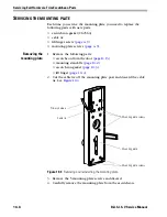
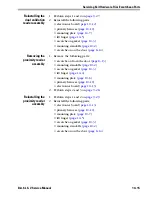
3. Place the spacer on the socket he4ad screw. Using a 3/32
″
hex
driver, reinstall the socket head screw.
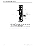
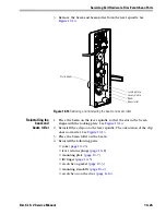
4. Route the motor harness into the groove in the escutcheon, as
shown in
Figure 10.8
.
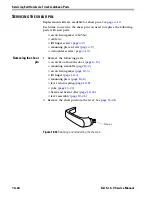
5. Reinstall the sounder onto the escutcheon. See
Figure 10.9
.
Figure 10.8
Routing the motor harness
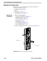
Locking plate
Locking lever
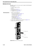
Pivot pin
Socket head screw
Motor harness
Motor assembly
Summary of Contents for B.A.S.I.S. V
Page 1: ...SERVICE MANUAL SERVICE MANUAL ...
Page 16: ...Figures xvi B A S I S V Service Manual ...
Page 48: ...Standard Functions and Parts 2 24 B A S I S V Service Manual ...
Page 66: ...Exit Hardware Trim Functions and Parts 3 18 B A S I S V Service Manual ...
Page 78: ...Shared Standard and Exit Hardware Trim Parts 4 12 B A S I S V Service Manual ...
Page 114: ...Servicing Standard Mortise Case Parts 6 20 B A S I S V Service Manual ...
Page 206: ...Servicing Exit Hardware Trim Escutcheon Parts 10 32 B A S I S V Service Manual ...
Page 238: ...Troubleshooting 12 12 B A S I S V Service Manual ...
Page 242: ...Lock History Event Types A 4 B A S I S V Service Manual ...
Page 244: ...Installation Instructions B 2 B A S I S V Service Manual ...


