Servicing Standard Outside Escutcheon Parts
B.A.S.I.S. V Service Manual
9–23
Reinstalling the
smart card reader
assembly
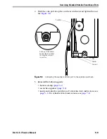
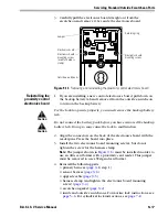
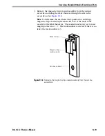
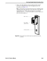
1. Orient the reader assembly and insert the flex cable through the slot
in the outside escutcheon. See
Figure 9.20
.
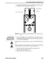
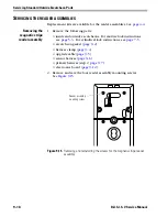
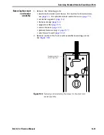
2. Position the smart card reader assembly on the reader gasket and
install the four reader assembly mounting screws. See
Figure 9.18
.
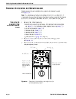
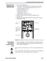
3. Reinstall the following parts:
■
electronics board (
page 9–13
)
■
primary harness (step 1,
page 9–8
)
■
sensor harness (
page 9–6
)
■
upgrade cable (
page 9–5
)
■
harness clamp (
page 9–4
)
■
escutcheon gasket (
page 9–2
)
■
inside and outside escutcheons. For mortise lock instructions, see
page 5–6
. For cylindrical lock instructions, see
page 7–8
.
Figure 9.20
Positioning the smart card reader assembly
Slot
Reader gasket
Flex cable
Smart card
reader assembly
Outside escutcheon
Summary of Contents for B.A.S.I.S. V
Page 1: ...SERVICE MANUAL SERVICE MANUAL ...
Page 16: ...Figures xvi B A S I S V Service Manual ...
Page 48: ...Standard Functions and Parts 2 24 B A S I S V Service Manual ...
Page 66: ...Exit Hardware Trim Functions and Parts 3 18 B A S I S V Service Manual ...
Page 78: ...Shared Standard and Exit Hardware Trim Parts 4 12 B A S I S V Service Manual ...
Page 114: ...Servicing Standard Mortise Case Parts 6 20 B A S I S V Service Manual ...
Page 206: ...Servicing Exit Hardware Trim Escutcheon Parts 10 32 B A S I S V Service Manual ...
Page 238: ...Troubleshooting 12 12 B A S I S V Service Manual ...
Page 242: ...Lock History Event Types A 4 B A S I S V Service Manual ...
Page 244: ...Installation Instructions B 2 B A S I S V Service Manual ...

