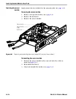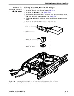
Servicing Standard Mortise Case Parts
6–2
B.A.S.I.S. V Service Manual
S
ERVICING
THE
MORTISE
CASE
Removing and
opening the mortise
case
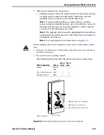
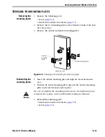
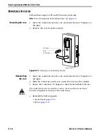
1. Remove the inside and outside trim from the door. Instructions
begin on
page 5–1
.
2. From the edge of the door, remove the two case mounting screws.
3. Remove the case from the door.
4. Set the case on a flat surface.
5. Remove the case cover screw from the mortise case spacer. Remove
the case spacer.
6. Remove the remaining four case cover screws. Carefully remove the
case cover. Many parts are spring loaded and may shift.
Closing and
reinstalling the
mortise case
1. Route the motor and sensor wires through the openings in the case.
2. Place the case cover on the case and install the four case cover
screws.
3. Install the mortise case spacer and the case cover screw.
4. Insert the mortise case into the mortise cavity, while feeding the
sensor and motor wires into the mortise cavity and out the sensor &
motor wire hole to the inside of the door.
Note:
If the armored front of the mortise case is not flush with the
door edge, remove the case and loosen the screws at the top and
bottom of the case. Adjust the bevel of the armored front of the
mortise case to match the bevel of the door. Tighten the screws and
insert the mortise case back into the mortise cavity.
5. Secure the mortise case with the case mounting screws.
6. Reinstall the inside and outside trim on the door. Instructions begin
on
page 5–1
.
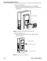
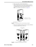
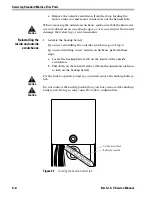
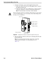
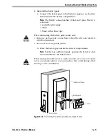
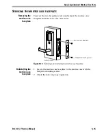
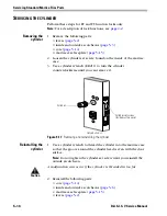
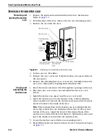
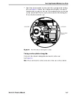
Figure 6.1
Removing and reinstalling the mortise case
Inside of door
Sensor & motor
wire hole and
wires
Mortise case
Mortise cavity
Location of bevel
adjusting screw
Bevel adjusting
screw
Case
mounting
screws
Summary of Contents for B.A.S.I.S. V
Page 1: ...SERVICE MANUAL SERVICE MANUAL ...
Page 16: ...Figures xvi B A S I S V Service Manual ...
Page 48: ...Standard Functions and Parts 2 24 B A S I S V Service Manual ...
Page 66: ...Exit Hardware Trim Functions and Parts 3 18 B A S I S V Service Manual ...
Page 78: ...Shared Standard and Exit Hardware Trim Parts 4 12 B A S I S V Service Manual ...
Page 114: ...Servicing Standard Mortise Case Parts 6 20 B A S I S V Service Manual ...
Page 206: ...Servicing Exit Hardware Trim Escutcheon Parts 10 32 B A S I S V Service Manual ...
Page 238: ...Troubleshooting 12 12 B A S I S V Service Manual ...
Page 242: ...Lock History Event Types A 4 B A S I S V Service Manual ...
Page 244: ...Installation Instructions B 2 B A S I S V Service Manual ...

