Installation Instructions for B.A.S.I.S. Mortise Locks
BEST ACCESS SYSTEMS
Indianapolis, Indiana
9
Installation Instructions for B.A.S.I.S. Mortise Locks
Installing the lock
13
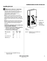
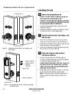
Make motor and sensor connections
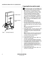
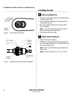
From the inside of the door, make the motor
connection, the key override sensor connection (EV
and FV functions)
†
, and the deadbolt sensor
connection (FV and LV functions).
Note 1:
It is physically possible to connect the key
override sensor connector from the mortise case to the
battery connector from the wire harness. To avoid this
mistake, connect only the connectors with matching wire
colors.
Note 2:
The upgrade cable is used for reprogramming
the lock’s firmware without removing the lock from the
door. This cable does not connect to a mating lock
connector.
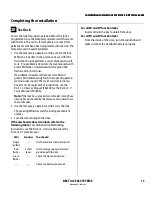
Caution:
When making the motor connection and
sensor connections, make sure:
■
there are no loose wire connections where the
wires are inserted into the connectors
■
the connectors are firmly mated.
† Key override sensing is optional for 35HG and
standard for 35HBV.
Wire connection
Colors
No. of
wires
No. of
pins
Motor
Yellow
Gray
2
2
Key override sensor
Gray
2
3
Deadbolt sensor
Blue
2
3
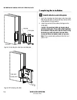
Figure 13 Making the motor connection and
sensor connections
Motor
connection
Key override
sensor connection
Inside of door
Deadbolt sensor
connection
Upgrade cable
Summary of Contents for B.A.S.I.S. V
Page 1: ...SERVICE MANUAL SERVICE MANUAL ...
Page 16: ...Figures xvi B A S I S V Service Manual ...
Page 48: ...Standard Functions and Parts 2 24 B A S I S V Service Manual ...
Page 66: ...Exit Hardware Trim Functions and Parts 3 18 B A S I S V Service Manual ...
Page 78: ...Shared Standard and Exit Hardware Trim Parts 4 12 B A S I S V Service Manual ...
Page 114: ...Servicing Standard Mortise Case Parts 6 20 B A S I S V Service Manual ...
Page 206: ...Servicing Exit Hardware Trim Escutcheon Parts 10 32 B A S I S V Service Manual ...
Page 238: ...Troubleshooting 12 12 B A S I S V Service Manual ...
Page 242: ...Lock History Event Types A 4 B A S I S V Service Manual ...
Page 244: ...Installation Instructions B 2 B A S I S V Service Manual ...


