Figures
B.A.S.I.S. V Service Manual
xiii
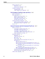
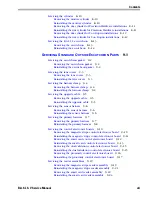
Removing the inside rose liner
7–15
Removing the outside rose liner
7–15
Reinstalling the outside rose liner
7–16
Reinstalling the inside rose liner
7–17
S
ERVICING
E
XIT
H
ARDWARE
T
RIM
P
ARTS
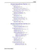
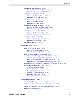
Removing and reinstalling the battery cover on the battery bracket
8–2
Removing and reinstalling the battery pack
8–4
Removing and reinstalling the battery bracket on the door
8–6
Removing and reinstalling the com port in the battery bracket
8–6
Removing and reinstalling the core
8–9
Mortise cylinder components
8–10
Rim cylinder components
8–11
Removing and reinstalling the rim cylinder for Precision Hardware installations
8–11
Removing and reinstalling the rim cylinder for Von Duprin installations
8–12
Removing and reinstalling the escutcheon
8–13
S
ERVICING
S
TANDARD
O
UTSIDE
E
SCUTCHEON
P
ARTS
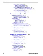
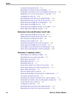
Removing and reinstalling the escutcheon gasket
9–2
Removing and reinstalling the lens covers (smart card reader shown)
9–3
Removing and reinstalling the harness clamp (smart card reader shown)
9–4
Removing and reinstalling the upgrade cable (smart card reader shown)
9–5
Removing and reinstalling the sensor harness (smart card reader shown)
9–6
Removing and reinstalling the primary harness from the electronics board (smart
card reader shown)
9–7
Disconnecting the sounder and com port from the outside escutcheon
9–8
Connecting the sounder and com port to the outside escutcheon
9–9
Removing and reinstalling the magnetic stripe control electronics board
9–10
Removing and reinstalling the smart card control electronics board
9–12
Disconnecting the flex cable from the smart card control electronics board
9–13
Connecting the flex cable to the smart card control electronics board
9–14
Removing and reinstalling the dual validation control electronics board
9–15
Removing and reinstalling the proximity control electronics board
9–17
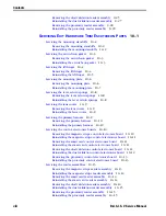
Removing and reinstalling the screws for the magnetic stripe reader assembly
9–19
Removing the magnetic stripe reader assembly from the outside escutcheon
9–20
Positioning the magnetic stripe reader assembly
9–21
Removing and reinstalling the screws for the smart card reader assembly
9–22
Summary of Contents for B.A.S.I.S. V
Page 1: ...SERVICE MANUAL SERVICE MANUAL ...
Page 16: ...Figures xvi B A S I S V Service Manual ...
Page 48: ...Standard Functions and Parts 2 24 B A S I S V Service Manual ...
Page 66: ...Exit Hardware Trim Functions and Parts 3 18 B A S I S V Service Manual ...
Page 78: ...Shared Standard and Exit Hardware Trim Parts 4 12 B A S I S V Service Manual ...
Page 114: ...Servicing Standard Mortise Case Parts 6 20 B A S I S V Service Manual ...
Page 206: ...Servicing Exit Hardware Trim Escutcheon Parts 10 32 B A S I S V Service Manual ...
Page 238: ...Troubleshooting 12 12 B A S I S V Service Manual ...
Page 242: ...Lock History Event Types A 4 B A S I S V Service Manual ...
Page 244: ...Installation Instructions B 2 B A S I S V Service Manual ...


