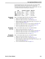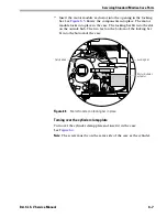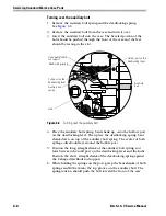
Servicing Standard Mortise Case Parts
6–14
B.A.S.I.S. V Service Manual
S
ERVICING
PARTS
IN
THE
MORTISE
CASE
Servicing the motor
module
Caution
Use extreme caution and wear safety glasses or goggles when
performing the steps below. Point the case away from you while
removing and reinstalling the upper auxiliary spring. The spring
may unexpectedly pop out and could injure you.
Removing the motor module
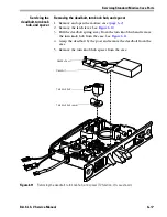
1. Remove and open the mortise case (
page 6–2
).
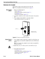
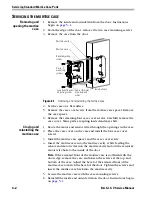
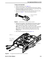
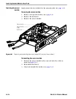
2. Rotate the locking bar and motor module. Remove the locking bar
from the case. See
Figure 6.9
.
3. Use a pair of needle-nosed pliers to carefully remove the upper
auxiliary spring from the case.
4. Remove the wire strain relief and motor module from the case.
5. Open the wire strain relief and remove the wires.
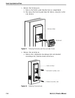
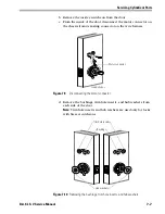
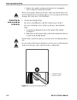
Figure 6.9
Removing and reinstalling the motor module
Auxiliary return lever
Wire strain relief
Top shank of the upper
auxiliary bolt spring
Locking bar
Motor module’s
actuator
Post
Summary of Contents for B.A.S.I.S. V
Page 1: ...SERVICE MANUAL SERVICE MANUAL ...
Page 16: ...Figures xvi B A S I S V Service Manual ...
Page 48: ...Standard Functions and Parts 2 24 B A S I S V Service Manual ...
Page 66: ...Exit Hardware Trim Functions and Parts 3 18 B A S I S V Service Manual ...
Page 78: ...Shared Standard and Exit Hardware Trim Parts 4 12 B A S I S V Service Manual ...
Page 114: ...Servicing Standard Mortise Case Parts 6 20 B A S I S V Service Manual ...
Page 206: ...Servicing Exit Hardware Trim Escutcheon Parts 10 32 B A S I S V Service Manual ...
Page 238: ...Troubleshooting 12 12 B A S I S V Service Manual ...
Page 242: ...Lock History Event Types A 4 B A S I S V Service Manual ...
Page 244: ...Installation Instructions B 2 B A S I S V Service Manual ...

