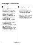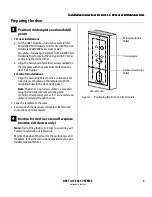
Installation Instructions for B.A.S.I.S. Cylindrical Locks
BEST ACCESS SYSTEMS
Indianapolis, Indiana
7
Installation Instructions for B.A.S.I.S. Cylindrical Locks
Installing the lock
8
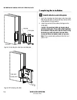
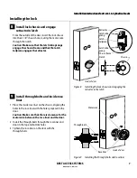
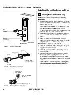
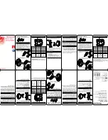
Install lock chassis and engage
retractor in latch
From the outside of the door, insert the lock chassis
into the 2 1/8
″
chassis hole, routing the motor wire
through the notch.
Caution:
Make sure that the latch tube prongs
engage the chassis frame and that the latch
tailpiece engages the retractor.
9
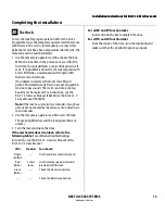
Install through-bolts and inside rose
liner
1 Place the inside rose liner on the chassis, aligning the
holes in the rose liner with the holes prepared in the
door.
Caution:
Make sure that there is clearance for the
motor wire between the rose liner and the door.
2 Install the through-bolts through the rose liner and
door in the top and bottom holes.
3 Tighten the rose liner on the door with the
through-bolts.
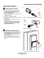
Figure 8
Installing the lock chassis and engaging the
retractor in the latch
Latch tube
prong
Retractor
Latch
tailpiece
Chassis
Chassis frame
Latch tube
prong
Notch
Inside of door
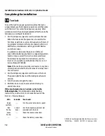
Figure 9
Installing the through-bolts and rose liner
Through-bolt
Motor wire
Inside of door
Rose liner
Summary of Contents for B.A.S.I.S. V
Page 1: ...SERVICE MANUAL SERVICE MANUAL ...
Page 16: ...Figures xvi B A S I S V Service Manual ...
Page 48: ...Standard Functions and Parts 2 24 B A S I S V Service Manual ...
Page 66: ...Exit Hardware Trim Functions and Parts 3 18 B A S I S V Service Manual ...
Page 78: ...Shared Standard and Exit Hardware Trim Parts 4 12 B A S I S V Service Manual ...
Page 114: ...Servicing Standard Mortise Case Parts 6 20 B A S I S V Service Manual ...
Page 206: ...Servicing Exit Hardware Trim Escutcheon Parts 10 32 B A S I S V Service Manual ...
Page 238: ...Troubleshooting 12 12 B A S I S V Service Manual ...
Page 242: ...Lock History Event Types A 4 B A S I S V Service Manual ...
Page 244: ...Installation Instructions B 2 B A S I S V Service Manual ...

